This thread has been locked.

If you have a related question, please click the "Ask a related question" button in the top right corner. The newly created question will be automatically linked to this question.

TMS320F28377D: ADC PRESCALE and ACQPS setting question

Part Number: TMS320F28377D

Hi there,

I am using the ADC module in the DSP 28377D, in Single ended mode, 12-bit resolution. I wanted to ask you if you could help confirming that my adc configuration is correct. 

1. Each ADC is configure as follow:

void ConfigureADC_A(void)
{
	EALLOW;

	//write configurations
	AdcaRegs.ADCCTL2.bit.PRESCALE = 0; 
    AdcSetMode(ADC_ADCA, ADC_RESOLUTION_12BIT, ADC_SIGNALMODE_SINGLE);

	//Set pulse positions to late
	AdcaRegs.ADCCTL1.bit.INTPULSEPOS = 1;

	//power up the ADC
	AdcaRegs.ADCCTL1.bit.ADCPWDNZ = 1;

	//delay for 1ms to allow ADC time to power up
	DELAY_US(1000);

	EDIS;
}

the question here is: by setting 

AdcaRegs.ADCCTL2.bit.PRESCALE = 0; 

knowing that in my program I have set

ClkCfgRegs.PERCLKDIVSEL.bit.EPWMCLKDIV = 0

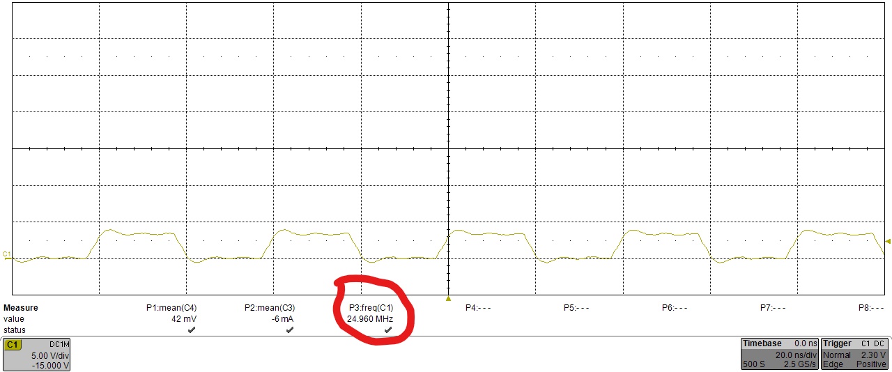
does it mean that the 1x ADC CLOCK period is = SYSCLK/1= (200MHz)^-1 = 5ns? this seems very small.

2.  I need to confirm that the calculation of the ADC parameter ACQPS is correct.

I can see that in the SPRUHM8C (pag. 1221) document TI gives a guideline on how to roughly estimate the acquisition window time "t":

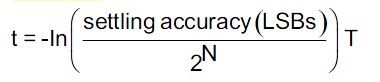
where the T on the right is the charging time constant of the sample and hold capacitor.

Based on the recommendations in  SPRUHM8C (pag. 1221) and the model of the ADC reported in the datasheet SPRS880C (p. 107, reported below)

then:

T = (Rs+Ron)*Ch.

Now, in my case the ADC input is connected to the output of an op-amp via a 200 Ohm resistor, like in the picture below


My question is, should I consider Rs = 200Ohm then? If so, I calculate T = (500+200Ohm)*14.5pF=10*10^-9s and the acquisition window time t = -ln(0.25/2^12)*T=100ns. 

Having, t=100ns=(ACQPS+1)*SYSCLK --> ACQPS = 100ns/5ns - 1 =19 (where SYSCLK=5ns, as the clock is 200MHz). 

In summary, I came up with:

1. one ADC CLK = 5ns, as

AdcaRegs.ADCCTL2.bit.PRESCALE = 0

2. ACQPS = 19, considering Rs=200Ohm (the resistance between the adc input and the op-amp output) and Ch and Ron given in the datasheet SPRS880C (p. 107).

Could you please confirm if my reasoning is correct? Especially in regards to point 2, and the Rs I consider for the calculation of the acquisition window.

Thank you very much for your time.

Leo

  • Hi Leo,

    I think your calculation of ADCCLK and ePWM CLK are correct, but the modules have a maximum clock rate. Assuming your System clock is 200MHz:

    For the ADC, the maximum clock rate is 50MHz, so you will want a prescale that is /4.

    For ePWM, the maximum clock rate is 100MHz, so you will want to enable the /2

    As far as the ADC S+H duration, yes, the 200 ohm resistor should be considered, and you have estimated the S+H correctly. Do note that the S+H estimation only holds in this case if you haven't intentionally added additional capacitance to the ADC input (which is something you may want to do). Also note that the S+H is calculated as ACQPS+1 SYSCLK cycles, so even if you change the ADC prescale to get ADCCLK = 50MHz, the ACQPS setting of 19 will still give you 100ns (assuming SYSCLK = 200MHz).
  • Hello Devin,

    Thank you so much for your help, it is really useful. It is good to know the limits on the ADC CLK and PWM CLK, I was not aware of this.

    1. I have double checked my program, and the settings are actually as follow:

    ClkCfgRegs.SYSCLKDIVSEL.bit.PLLSYSCLKDIV = 1 // (see Table 2-149, p.300 SPRUHM8C)

    This means that my system clock is 200MHz /2 = 100MHz.

    2. As a consequence, with:

    ClkCfgRegs.PERCLKDIVSEL.bit.EPWMCLKDIV = 1
    

    my PWM clock rate is 100MHz, which is the maximum acceptable.

    3. At this stage, being my SYS CLK = 100MHz (point 1) I can set

    AdcaRegs.ADCCTL2.bit.PRESCALE = 2; 

    so that my ADC CLK is SYSCLK(100MHz)/2 = 50MHz

    4. Considering that my S+H time is t = 100ns, as calculated in my previous question, now that I discovered that my SYSCLK is 100MHz, then

    (ACQPS+1)*(1/100MHz) = 100ns --> ACQPS = 10 - 1 = 9

    so in theory I can use a much lower ACQPS than what I calculated in my previous question.

    If you could please give me your opinion on my reasoning it would be fantastic. 

    Thank you so much again.

    Leo


  • Hi Leo,

    Almost. ADCCLK is based off of SYSCLK, so the PRESCALE needs to be set to /4 if SYSCLK is 200MHz (no matter what the ePWM clock is set to).

    Similarly, even with ADCCLK of 50MHz, the S+H logic is clocked by SYSCLK, so you still want ACQPS of 19 to give you 5ns*(19+1) = 100ns of S+H duration. This is independent of both the ADCCLK and the ePWM clock. (This works because the ADCCLK is not actually free running. When the trigger occurs the S+H logic is clocked for ACQPS+1 cycles and then the rising edge of the ADCCLK starts immediately after the S+H is finished. Once the ADC conversion is clocked for some number of ADCCLK cycles, the ADC finishes and the ADCCLK goes back to sleep until after the end of another S+H phase. It is done this way so that there is no jitter from triggers coming from the CPU or ePWM clock domain...the sample always starts immediately on the next SYSCLK edge).
  • Hello Devin,

    Thank you, your feedback and explanations are great.

    So, I think that my misunderstanding before was due to the fact that I thought that by setting 

    ClkCfgRegs.SYSCLKDIVSEL.bit.PLLSYSCLKDIV = 1 

    the system clock becomes 200MHz/2 = 100MHz, but it is not the case, as such command only influences the ePWM clock. So by leaving:

    ClkCfgRegs.PERCLKDIVSEL.bit.EPWMCLKDIV = 1

    then the PWM is clocked at 100MHz.

    However the ADC clock is still based on the SYS CLK of 200MHz, so to have my S+H time of t = 100ns, I need to calculate ACQPS from:

    100ns = (ACQPS+1)*SYSCLK = (ACQPS+1)*1/200MHz --> ACQPS = 19

    as calculated at the beginning. 

    Not forgetting that to have the ADC clocking at 50MHz I have to set:

    AdcaRegs.ADCCTL2.bit.PRESCALE = 6; // i.e. SYSCLK(200MHz)/4

    Obviously, my assumption of a SYS CLK = 200MHz comes from the fact that I am using a TMS320F28377D...

    Thanks again,

    Leo

  • Hi Leo,

    Yeah, that all looks good.  

    I would recommend that you do check the SW settings for the PLL along with whatever HW you are using to ensure that you are indeed getting 200MHz SYSCLK.  You can also verify this experimentally by enabling XCLKOUT and then measuring with a scope or frequency counter.  

  • Hello Devin,

    Thanks a lot for your reply. 

    I tried to verify if my SYSCLK, i.e. CPU1 CLK, is 200MHz, 

    As you have suggested, and the SPRUHM8C says on pag. 107 

    So, I have configured GPIO73 as follow:

    	GpioCtrlRegs.GPCPUD.bit.GPIO73 = 1; // Enable pullup on GPIO73
    	GpioCtrlRegs.GPCMUX1.bit.GPIO73 = 3; // GPIO73 = XCLKOUT (MUX = 3, Table 4-3 of SPRS880C, pag. 40)
    	GpioCtrlRegs.GPCDIR.bit.GPIO73 = 1; // GPIO73 configured as an OUTPUT

    and I have set: 

    ClkCfgRegs.XCLKOUTDIVSEL.bit.XCLKOUTDIV=0; // divide by /1 (this is set =3, i.e. /8 by default)
    
    ClkCfgRegs.CLKSRCCTL3.bit.XCLKOUTSEL=2; // CPU1.SYSCLK Table 2-142 pag. 293 SPRUHM8C; selects the source for XCLKOUT 

    When I connect the scope probe on the GPIO73, this is what I see (note that the bandwidth of the scope is only 20MH, that is why I see a sine wave rather than a square wave in this picture):

    So, I believe that this is the confirmation that my SYSCLK indeed is 200MHz (althought I had to set to ClkCfgRegs.XCLKOUTDIVSEL.bit.XCLKOUTDIV=0 in order to display it correctly).

    Thank you

    Leo

  • Hi Leo,

    You can also set the XCLKOUT divider to /8, but that will only get you to 25MHz.

    You could also intentionally set the PLL divider up a few settings (maybe to something like /16) to observe if the SYSCLK is as expected.

    It isn't really necessary, but could be a good sanity check / debug step.
  • Hi Devin,

    Thanks again. I had one more try, with

    and leaving unchanged the PLLSYSCLKDIV as per below

    this is what I get

    seems to work as expected.

    Thanks

    Leo