This thread has been locked.

If you have a related question, please click the "Ask a related question" button in the top right corner. The newly created question will be automatically linked to this question.

TMS320F28377S: SDFM with AMC1204

Part Number: TMS320F28377S
Other Parts Discussed in Thread: AMC1204, CONTROLSUITE

I'm trying to work on using a Sigma Delta Filter Module to measure an isolated voltage. From a high level, I would like to read a voltage at 500 Hz.

My hardware is a AMC1204 and the TMS320F28377S Launchpad.

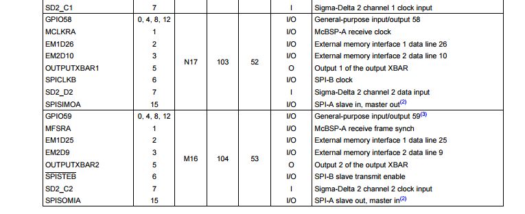
The first thing I would like to figure out is how to properly hook these up. I would like to connect to GPIO58 and GPIO59 for the second SDFM (channel 2) on the processor. Do these connect to pins 6 and 7 on the AMC1204? I guess I am wondering how to generate the 20 MHz "Modulator Clock Input" on the AMC1204, and the "Sigma-Delta 2 channel 2 clock input" on the F28377S.

I read in the TRM that PWM12 can be used to synchronize things, but what is being used to generate the Sigma Delta Clock for the chip? 

  • Daniel,

    There are two package options available for AMC1204. I believe you are working with 8-Pin SOIC package.

    AMC1204. pin 7 (CLKIN) should be connected to SDFM clock channel
    AMC1204. pin 6 (DATA) should be connected to SDFM data channel and
    Any PWM channel can provide 20 MHz clock to AMC1204.pin7 (CLKIN input)

    Please refer to Pg 1 of AMC1304 DS for reference schematics.

    Regards,
    Manoj
  • Ok, great. Thank you.

    So what I did was exactly what is mentioned in the AMC1304 Datasheet in Figure 58.

    I am using EPWM11A to generate a 10MHz Square wave that is going into the CLKIN pin on the AMC1204 chip and the GPIO59 / Launchpad Pin 14 / SD2_C2 pin on the 28377S Launchpad. When I input a voltage from a signal generator, I see activity on the DATA pin as expected (when I measure it with a scope), but when I try to read the register in the 28377S I don't get anything.

    Here is my code (I am leaving out the 10 MHz square wave ePWM initialization because I measured that with a scope, so I know it is working right):

    1) Code to initialize the Sigma Delta Inputs which runs once on startup, I first try to configure GPIO58 and GPIO59 to be muxed to input 7 which should be the SD2_D2 and SD2_C2 functionality. Then I go through configuring the second Sigma Delta Module on the processor... whether right or wrong.

    2071

    2072

          //Initialize GPIOs

    2073

          EALLOW;

    2074

          GpioCtrlRegs.GPBGMUX2.bit.GPIO59 = 2U;

    2075

          GpioCtrlRegs.GPBMUX2.bit.GPIO59 = 0U;

    2076

    2077

          //GpioCtrlRegs.GPBDIR.all |= 0x8000000;

    2078

          EDIS;

    2079

          EALLOW;

    2080

          GpioCtrlRegs.GPBGMUX2.bit.GPIO58 = 2U;

    2081

          GpioCtrlRegs.GPBMUX2.bit.GPIO58 = 0U;

    2082

    2083

          //GpioCtrlRegs.GPBDIR.all &= 0xFBFFFFFF;

    2084

          EDIS;

    2085

    2086

          //Initialize SDFM 2

    2087

          EALLOW;

    2088

    2089

          //SET SDMFILEN

    2090

          //Set Master Filter Enable

    2091

          Sdfm2Regs.SDMFILEN.bit.MFE = 1U;

    2092

    2093

          //SET SDCTLPARM2

    2094

          //Set Mode of Sigma Delta Filter Module

    2095

          Sdfm2Regs.SDCTLPARM2.bit.MOD = 0U;

    2096

    2097

          //SET SDDFPARM2

    2098

          //Set Data Filter Structure

    2099

          Sdfm2Regs.SDDFPARM2.bit.SST = 2U;

    2100

    2101

          //Enable Filter for this

    2102

          Sdfm2Regs.SDDFPARM2.bit.FEN = 1U;

    2103

    2104

          //Set Oversampling Ratio to (255 + 1)

    2105

          Sdfm2Regs.SDDFPARM2.bit.DOSR = 255U;

    2106

    2107

          //SET SDIPARM2

    2108

          //Set Width of data field to 32 bit Two's complement

    2109

          Sdfm2Regs.SDIPARM2.bit.DR = 1U;

    2110

    2111

          //Skip SET SDCMPH2

    2112

          //Skip SET SDCMPL2

    2113

          //Skip SET SDCPARM2

    2114

          EDIS;

    2) Code to read the Sigma Delta Register at 500Hz and write it to a variable called "SDDATA2_Raw" that I am going to scope. Right now the output is pure zeros so I know that something isn't right. I know that I should be reading this as a int32, but I am just looking for something that is a non-zero bit value.

    1751

      /* Event: '<S6>:394' */

    1752

      {

    1753

        uint32_T *memindsrc = (uint32_T *) (&Sdfm2Regs.SDDATA2.all);

    1754

        uint32_T *meminddst = (uint32_T *) (&rtb_MemoryCopy);

    1755

        *(uint32_T *) (meminddst) = *(uint32_T *) (memindsrc);

    1756

      }

    1757

    1758

      /* DataStoreWrite: '<S2>/Read_SDDATA2_Raw' */

    1759

      SDDATA2_Raw = rtb_MemoryCopy;

    Any ideas where I am going wrong. I think that I have the sigma delta signals going into the 28377S pins correctly since I have looked at them on a scope. Am I initializing the SDFM correctly?

  • Daniel,

    Is there any reason why you want to use bit-field? TI provides drivers for SDFM which will make you life easier.

    Have you had a chance to look into SDFM example code available in controlSuite?

    Path: <controlSUITE>\device_support\F2837xS\v210\F2837xS_examples_Cpu1\sdfm_filters_sync_cpu

    Regards,
    Manoj
  • Hi Manoj,

    I have looked at the drivers in Control Suite. I want to use the bit fields because I'm expecting that the SDFM interrupt driver ("Sdfm_configureInterrupt") won't work for my application, so I wanted to start without the drivers.

    If possible, I'm wondering if I can set up the SDFM to capture data at a very high sample rate, then decimate the data further in an interrupt down to where I can transmit it at a sample rate of 500 or 1000 Hz. Similar to an ADC operating at 1000 Hz.

    Thanks,

    Daniel

  • Daniel,

    SDFM data rate is controlled by SDCLK and OSR. It doesn't depend upon how fast you read the SDFM filter. It is important to know that SDDATA register changes at the rate of (SDCLK freq / OSR).

    I believe you are trying to avoid interrupt as SDFM interrupts CPU very frequently. Am I correct?

    Regards,
    Manoj
  • Correct.
    Since I have a SDCLK of 10 MHz and an OSR of 256, I have a 39kHz sample rate. I would like to do one of two things:
    1) Interrupt on the 39kHz data that is coming in from SDDATA and decimate it with a digital filter to where there is no frequency content above 250 Hz. I then read the decimated SDDATA variable at 500 Hz.
    2) Put an analog filter on the input of the AMC1204 chip which filters out all data above 250Hz, then read SDDATA asychronously at 500 Hz (or whatever speed I choose) even though the data is coming in at 39kHz.

    I would be ok with the interrupt as long as I am doing very little in the interrupt (small filtering, it could even be moved to the CLA).

    What I need help with is getting it so I get data out of the SDDATA register. I think the SDFM is not configured correctly with the code I have above.

    Daniel
  • Daniel,

    1) Your GPIO Mux configuration is wrong.

    GPIO58 can be configured as SD1_D4
    GPIO59 can be configured as SD1_C4

    GpioCtrlRegs.GPBGMUX2.bit.GPIO58 = 1U;
    GpioCtrlRegs.GPBGMUX2.bit.GPIO59 = 1U;

    GpioCtrlRegs.GPBMUX2.bit.GPIO58 = 3U;
    GpioCtrlRegs.GPBMUX2.bit.GPIO59 = 3U;

    2) Your filter configuration settings are wrong. You have configured SDFM2.Filterchannel2 whereas you have to configure SDFM1.FilterChannel4 (SD1_D4 / SD1_C4)

    You configure SDFM1.Filterchannel4 with below statements.

    Sdfm1Regs.SDCTLPARM4.bit.MOD = 0U;

    Sdfm1Regs.SDDFPARM4.bit.SST = 2U;

    Sdfm1Regs.SDDFPARM4.bit.FEN = 1U;

    Sdfm1Regs.SDDFPARM4.bit.DOSR = 255U;

    Sdfm1Regs.SDIPARM4.bit.DR = 1U;


    I would still recommend you use SDFM drivers. All you need to do is don't enable SDFM data acknowledge interrupt.

    Regards,
    Manoj
  • Hi Manoj,

    Thanks for the response. Are you sure that GPIO58 and GPIO59 are for SDFM1 channel4? When I look in the datasheet for the TMS28377S datasheet, I see the following... (is there another pin that GPIO58 and GPIO59 can be configured to)?

    I'm working on integrating the SDFM drivers, but it is a little finicky in a MATLAB / Simulink Embedded Coder environment. That is initially why I was trying to manually assign the registers. That way I could verify that the Sigma Delta Module was working properly independent of MATLAB environment problems / issues with integrating external drivers.

    Daniel

  • Daniel,

    My bad. I was looking into F280049 DS instead of F28377s.

    Ignore the SDFM setting statements I mentioned above. But, GPIOMUX configurations are still correct.

    Regards,
    Manoj
  • Hi Manoj,

    I reconfigured the GPIO's properly.

    GpioCtrlRegs.GPBGMUX2.bit.GPIO58 = 1U;
    GpioCtrlRegs.GPBGMUX2.bit.GPIO59 = 1U;

    GpioCtrlRegs.GPBMUX2.bit.GPIO58 = 3U;
    GpioCtrlRegs.GPBMUX2.bit.GPIO59 = 3U;

    Then configuring the SDFM with the following:

    Sdfm2Regs.SDCTLPARM2.bit.MOD = 0U;
    Sdfm2Regs.SDDFPARM2.bit.SST = 2U;
    Sdfm2Regs.SDDFPARM2.bit.FEN = 1U;
    Sdfm2Regs.SDDFPARM2.bit.DOSR = 255U;
    Sdfm2Regs.SDIPARM2.bit.DR = 1U;

    Then from here is it just a read of the SDDATA2 address (Sdfm2Regs.SDDATA2.all or 0x5EA6)?

    I'm still actually not getting any output when I read this (just a zero). Are there any other bits that I need to configure to "turn on" the SDFM from here? I have tried enabling the MFE bit, but it isn't making a difference for me.

    Sdfm2Regs.SDMFILEN.bit.MFE = 1U;

  • Daniel,

    In 32-bit format, your SDFM2. Filter channel 2 result is supposed it read from 0x5EA6 and 0x5EA7

    In 16-bit format, your SDFM2. Filter channel 2 result is supposed it read from 0x5EA7.

    Please enable Sdfm2Regs.SDCPARM1.bit.MFIE = 1; I'm wondering whether you're getting modulator clock failure? For debug purpose enable interrupt flag for data acknowledge as well and then check SDIFLG register.

    Regards,
    Manoj
  • Also, check the SDFM2 registers in memory window to make sure you configurations are going though. If the configurations are still in default state, you might not have enable EALLOW.

    Regards,
    Manoj
  • Hi Manoj,

    When I look at the CCS Debug session, I can see that the GPIO settings have changed, but I see all zeros in the Sdfm2Regs.

    I am using EALLOW and EDIS in these statements. Do you know what could be preventing the Sdfm2Regs settings from going through? Do I need to set those before I set the GPIOs?

    Thanks,

    Dan

  • Daniel,

    Have you enabled module clock to both SDFM1 and SDFM2?

    These instructions enable module clock.
    CpuSysRegs.PCLKCR6.bit.SD1 = 1;
    CpuSysRegs.PCLKCR6.bit.SD2 = 1;

    Send a snapshot of SDFM register in memory window

    Regards,
    Manoj
  • I had not done that. Bingo. It is working now!

    Thank you.