This thread has been locked.

If you have a related question, please click the "Ask a related question" button in the top right corner. The newly created question will be automatically linked to this question.

LAUNCHXL-F28377S: PWM configuration problem (PWM10 and PWM11)

Part Number: LAUNCHXL-F28377S


Hello

I have problem regarding configuration PWM10 and PWM11 on LaunchPad_F28377S to generate signals.

Based on example epwm_up_aq_cpu01.c I can configure PWM 4,6,8 but I can't do this for PWM 10,11.

Bellow my code. Maybe somebody help me with this issue. I sent a lot of time to solve it.

Best Regards

Dariusz

#include "F28x_Project.h"
#include "F2837xS_Examples.h"

CpuSysRegs.PCLKCR2.bit.EPWM10=1;  // enable PWM10

EALLOW;
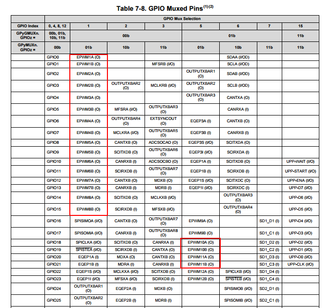
GpioCtrlRegs.GPAPUD.bit.GPIO18 = 1; // Disable pull-up on GPIO18 (EPWM10A)
GpioCtrlRegs.GPAPUD.bit.GPIO19 = 1; // Disable pull-up on GPIO19 (EPWM10B)
GpioCtrlRegs.GPAMUX2.bit.GPIO18 = 1; // Configure GPIO2 as EPWM10A
GpioCtrlRegs.GPAMUX2.bit.GPIO19 = 1; // Configure GPIO3 as EPWM10B
EDIS;

EPwm10Regs.TBPRD = 3125; // Set timer period
EPwm10Regs.TBPHS.bit.TBPHS = 0x0000; // Phase is 0
EPwm10Regs.TBCTR = 0x0000; // Clear counter

EPwm10Regs.TBCTL.bit.CTRMODE = 2; // Count up-down
EPwm10Regs.TBCTL.bit.PHSEN = 0; // Disable phase loading
EPwm10Regs.TBCTL.bit.HSPCLKDIV = TB_DIV2; // Clock ratio to SYSCLKOUT
EPwm10Regs.TBCTL.bit.CLKDIV = TB_DIV2; // Slow just to observe on

EPwm10Regs.CMPA.bit.CMPA =1562;
EPwm10Regs.CMPB.bit.CMPB =1562;

EPwm10Regs.AQCTLA.bit.CAU = 2; // Set PWM2A on Zero
EPwm10Regs.AQCTLA.bit.CAD = 1;
EPwm10Regs.AQCTLB.bit.CAU = 2; // Set PWM2B on Zero
EPwm10Regs.AQCTLB.bit.CAD = 1;

EPwm10Regs.DBCTL.bit.OUT_MODE = 3;
EPwm10Regs.DBCTL.bit.POLSEL = 1;
EPwm10Regs.DBCTL.bit.IN_MODE = 0;
EPwm10Regs.DBRED.bit.DBRED = 50;
EPwm10Regs.DBFED.bit.DBFED = 50; 

  • Hi Dariusz,

    Can you elaborate on how this doesn't work? Does the software fail to compile? Does the code run, but the ePWM10 and ePWM11 registers don't get configured correctly? Does the code appear to run correctly, but you don't see a signal on the device pin? Do you see a signal on the device pin, but it doesn't appear to reach the intended header location? Something else?
  • Dear David

    There are my answers regarding your question:

    1. Does the software fail to compile?.

    No. I don't have any errors during compilation stage.

    2. Does the code run, but the ePWM10 and ePWM11 registers don't get configured correctly?

    I compared register status between PWM2 and PWM10. There are configured the some way.

    The results are: the PWM pulses I can see on PWM2 but PWM10 doesn't work. Bellow the register status.

    Does the code appear to run correctly, but you don't see a signal on the device pin?

    Yes.

    Do you see a signal on the device pin, but it doesn't appear to reach the intended header location?

    I don't know what do you mine.

    I made the test. I used GPIO18 i 19 (PWM10)  as toggle mode. On the output I observed signals. So the channels work correctly

    Best Regards

    Dariusz

  • Hi Dariusz,

    Could this be do to the mux positions of ePWM10 and 11?

    The mux positions for both are the same, but you will need to set the GMUX to 1 for ePWM 10 and 11.