Tool/software: TI C/C++ Compiler
Hello,
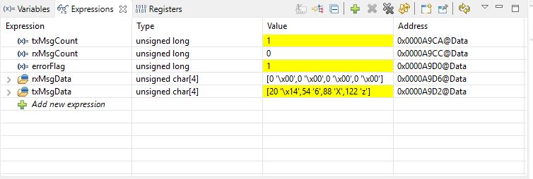
I want to test Can bus by using can_external_transmit.c
and I used 2 of mcp2551(can tranceiver) with LAUNCHXL-F28377S
and the result is
this is my source code
//########################################################################### // // FILE: can_external_transmit.c // // TITLE: Example to demonstrate CAN external transmission // //! \addtogroup cpu01_example_list //! <h1>CAN-A to CAN-B External Transmit (can_external_transmit)</h1> //! //! This example initializes CAN module A and CAN module B for external //! communication. CAN-A module is setup to transmit incrementing data for "n" //! number of times to the CAN-B module, where "n" is the value of TXCOUNT. //! CAN-B module is setup to trigger an interrupt service routine (ISR) when //! data is received. An error flag will be set if the transmitted data doesn't //! match the received data. //! //! \note Both CAN modules on the device need to be //! connected to each other via CAN transceivers. //! //! \b External \b Connections \n //! - CANA is on GPIO31 (CANTXA) and GPIO30 (CANRXA) //! - CANB is on GPIO8 (CANTXB) and GPIO10 (CANRXB) //! //! \b Watch \b Variables \n //! - TXCOUNT - Adjust to set the number of messages to be transmitted //! - txMsgCount - A counter for the number of messages sent //! - rxMsgCount - A counter for the number of messages received //! - txMsgData - An array with the data being sent //! - rxMsgData - An array with the data that was received //! - errorFlag - A flag that indicates an error has occurred //! // //########################################################################### // $TI Release: F2837xS Support Library v210 $ // $Release Date: Tue Nov 1 15:35:23 CDT 2016 $ // $Copyright: Copyright (C) 2014-2016 Texas Instruments Incorporated - // http://www.ti.com/ ALL RIGHTS RESERVED $ //########################################################################### // // Included Files // #include "F28x_Project.h" // Device Headerfile and Examples Include File #include <stdint.h> #include <stdbool.h> #include "inc/hw_types.h" #include "inc/hw_memmap.h" #include "inc/hw_can.h" #include "driverlib/can.h" // // Defines // #define TXCOUNT 100 #define MSG_DATA_LENGTH 4 #define TX_MSG_OBJ_ID 1 #define RX_MSG_OBJ_ID 1 // // Globals // volatile unsigned long i; volatile uint32_t txMsgCount = 0; volatile uint32_t rxMsgCount = 0; volatile uint32_t errorFlag = 0; unsigned char txMsgData[4]; unsigned char rxMsgData[4]; tCANMsgObject sTXCANMessage; tCANMsgObject sRXCANMessage; // // Function Prototypes // __interrupt void canbISR(void); // // Main // void main(void) { // // Initialize System Control: // PLL, WatchDog, enable Peripheral Clocks // InitSysCtrl(); // // Initialize GPIO and configure GPIO pins for CANTX/CANRX // on module A and B // InitGpio(); // // Setup GPIO pin mux for CAN-A TX/RX and CAN-B TX/RX // /*GPIO_SetupPinMux(30, GPIO_MUX_CPU1, 1); //GPIO30 - CANRXA GPIO_SetupPinOptions(30, GPIO_INPUT, GPIO_ASYNC); GPIO_SetupPinMux(31, GPIO_MUX_CPU1, 1); //GPIO31 - CANTXA GPIO_SetupPinOptions(31, GPIO_OUTPUT, GPIO_PUSHPULL); GPIO_SetupPinMux(10, GPIO_MUX_CPU1, 2); //GPIO10 - CANRXB GPIO_SetupPinOptions(10, GPIO_INPUT, GPIO_ASYNC); GPIO_SetupPinMux(8, GPIO_MUX_CPU1, 2); //GPIO8 - CANTXB GPIO_SetupPinOptions(8, GPIO_OUTPUT, GPIO_PUSHPULL);*/ GPIO_SetupPinMux(18, GPIO_MUX_CPU1, 3); //PIN76-J8 - CANRXA GPIO_SetupPinOptions(18, GPIO_INPUT, GPIO_ASYNC); GPIO_SetupPinMux(19, GPIO_MUX_CPU1, 3); //PIN75-J8 - CANTXA GPIO_SetupPinOptions(19, GPIO_OUTPUT, GPIO_PUSHPULL); GPIO_SetupPinMux(21, GPIO_MUX_CPU1, 3); //PIN 33-J4 - CANRXB GPIO_SetupPinOptions(17, GPIO_INPUT, GPIO_ASYNC); GPIO_SetupPinMux(20, GPIO_MUX_CPU1, 3); //PIN 34-J4 - CANTXB GPIO_SetupPinOptions(16, GPIO_OUTPUT, GPIO_PUSHPULL); // // Initialize the CAN controllers // CANInit(CANA_BASE); CANInit(CANB_BASE); // // Setup CAN to be clocked off the PLL output clock // CANClkSourceSelect(CANA_BASE, 0); // 500kHz CAN-Clock CANClkSourceSelect(CANB_BASE, 0); // 500kHz CAN-Clock // // Set up the CAN bus bit rate to 500kHz for each module // This function sets up the CAN bus timing for a nominal configuration. // You can achieve more control over the CAN bus timing by using the // function CANBitTimingSet() instead of this one, if needed. // Additionally, consult the device data sheet for more information about // the CAN module clocking. // CANBitRateSet(CANA_BASE, 200000000, 500000); CANBitRateSet(CANB_BASE, 200000000, 500000); // // Enable interrupts on the CAN B peripheral. // CANIntEnable(CANB_BASE, CAN_INT_MASTER | CAN_INT_ERROR | CAN_INT_STATUS); // // Clear all interrupts and initialize PIE vector table: // Disable CPU interrupts // DINT; // // Initialize the PIE control registers to their default state. // The default state is all PIE interrupts disabled and flags // are cleared. // InitPieCtrl(); // // Disable CPU interrupts and clear all CPU interrupt flags // IER = 0x0000; IFR = 0x0000; // // Initialize the PIE vector table with pointers to the shell Interrupt // Service Routines (ISR). // This will populate the entire table, even if the interrupt // is not used in this example. This is useful for debug purposes. // InitPieVectTable(); // // Interrupts that are used in this example are re-mapped to // ISR functions found within this file. // This registers the interrupt handler in PIE vector table. // EALLOW; PieVectTable.CANB0_INT = canbISR; EDIS; // // Enable the CAN-B interrupt on the processor (PIE). // PieCtrlRegs.PIEIER9.bit.INTx7 = 1; IER |= M_INT9; EINT; // // Enable the CAN-B interrupt signal // CANGlobalIntEnable(CANB_BASE, CAN_GLB_INT_CANINT0); // // Initialize the transmit message object used for sending CAN messages. // Message Object Parameters: // Message Identifier: 0x5555 // Message ID Mask: 0x0 // Message Object Flags: None // Message Data Length: 4 Bytes // Message Transmit data: txMsgData // sTXCANMessage.ui32MsgID = 0x5555; sTXCANMessage.ui32MsgIDMask = 0; sTXCANMessage.ui32Flags = 0; sTXCANMessage.ui32MsgLen = MSG_DATA_LENGTH; sTXCANMessage.pucMsgData = txMsgData; // // Initialize the receive message object used for receiving CAN messages. // Message Object Parameters: // Message Identifier: 0x5555 // Message ID Mask: 0x0 // Message Object Flags: Receive Interrupt // Message Data Length: 4 Bytes // Message Receive data: rxMsgData // sRXCANMessage.ui32MsgID = 0x5555; sRXCANMessage.ui32MsgIDMask = 0; sRXCANMessage.ui32Flags = MSG_OBJ_RX_INT_ENABLE; sRXCANMessage.ui32MsgLen = MSG_DATA_LENGTH; sRXCANMessage.pucMsgData = rxMsgData; CANMessageSet(CANB_BASE, RX_MSG_OBJ_ID, &sRXCANMessage, MSG_OBJ_TYPE_RX); // // Initialize the transmit message object data buffer to be sent // txMsgData[0] = 0x12; txMsgData[1] = 0x34; txMsgData[2] = 0x56; txMsgData[3] = 0x78; // // Start CAN module A and B operations // CANEnable(CANA_BASE); CANEnable(CANB_BASE); // // Transmit messages from CAN-A to CAN-B // for(i = 0; i < TXCOUNT; i++) { // // Check the error flag to see if errors occurred // if(errorFlag) { asm(" ESTOP0"); } // // Verify that the number of transmitted messages equal the number of // messages received before sending a new message // if(txMsgCount == rxMsgCount) { // // Transmit Message // CANMessageSet(CANA_BASE, TX_MSG_OBJ_ID, &sTXCANMessage, MSG_OBJ_TYPE_TX); txMsgCount++; } else { errorFlag = 1; } // // Delay 0.25 second before continuing // DELAY_US(1000 * 250); // // Increment the value in the transmitted message data. // txMsgData[0] += 0x01; txMsgData[1] += 0x01; txMsgData[2] += 0x01; txMsgData[3] += 0x01; } // // Stop application // asm(" ESTOP0"); } // // CAN B ISR - The interrupt service routine called when a CAN interrupt is // triggered on CAN module B. // __interrupt void canbISR(void) { uint32_t status; // // Read the CAN-B interrupt status to find the cause of the interrupt // status = CANIntStatus(CANB_BASE, CAN_INT_STS_CAUSE); // // If the cause is a controller status interrupt, then get the status // if(status == CAN_INT_INT0ID_STATUS) { // // Read the controller status. This will return a field of status // error bits that can indicate various errors. Error processing // is not done in this example for simplicity. Refer to the // API documentation for details about the error status bits. // The act of reading this status will clear the interrupt. // status = CANStatusGet(CANB_BASE, CAN_STS_CONTROL); // // Check to see if an error occurred. // if(((status & ~(CAN_ES_RXOK)) != 7) && ((status & ~(CAN_ES_RXOK)) != 0)) { // // Set a flag to indicate some errors may have occurred. // errorFlag = 1; } } // // Check if the cause is the CAN-B receive message object 1 // else if(status == RX_MSG_OBJ_ID) { // // Get the received message // CANMessageGet(CANB_BASE, RX_MSG_OBJ_ID, &sRXCANMessage, true); // // Getting to this point means that the RX interrupt occurred on // message object 1, and the message RX is complete. Clear the // message object interrupt. // CANIntClear(CANB_BASE, RX_MSG_OBJ_ID); // // Increment a counter to keep track of how many messages have been // received. In a real application this could be used to set flags to // indicate when a message is received. // rxMsgCount++; // // Since the message was received, clear any error flags. // errorFlag = 0; } // // If something unexpected caused the interrupt, this would handle it. // else { // // Spurious interrupt handling can go here. // } // // Clear the global interrupt flag for the CAN interrupt line // CANGlobalIntClear(CANB_BASE, CAN_GLB_INT_CANINT0); // // Acknowledge this interrupt located in group 9 // PieCtrlRegs.PIEACK.all = PIEACK_GROUP9; } // // End of File //