This thread has been locked.

If you have a related question, please click the "Ask a related question" button in the top right corner. The newly created question will be automatically linked to this question.

CCS/LAUNCHXL-F28377S: 2837x_rfft_adc_rt

Expert 1985 points

Part Number: LAUNCHXL-F28377S

Tool/software: Code Composer Studio

Hi,

I have some questions about “2837x_rfft_adc_rt”:

1-I do not find ADC_SAMPLING_FREQ variable initialization, how much is it?

#define F_PER_SAMPLE    (ADC_SAMPLING_FREQ/(float)RFFT_SIZE)

2- main.c :

...

//! External Connections:

//! Connect A0 (pin 9) to EPWM2A (pin 53) on the F2837x controlCARD. Refer to the

//! board schematic for pin positioning.

//! \note  The ADC will sample a 50% duty cycle 1KHz wave (EPWM2A) at 100KHz

//! and run the FFT on it. Since the input is a square wave, you will

//! see the fundamental frequency, 1KHz, at the 5th bin 

//! (5*fs/N = 5*100K/512 = 976.5) and all its odd harmonics.

...

The frequency of EPWM2A is 500Hz and when I connect EPWM2A to ADC pin A0,

freq = F_PER_SAMPLE * (float)j;

the frequency of input signal is 500Hz, but the final value in the CCS is, freq = 976.5 

, why?

3-What is maximum input frequency for this example? (considering the 2*f Nyquist rate)

   F_input_maximum=? KHz

Thanks & best regards,

Amin

  • Hi,

    amin said:

    1-I do not find ADC_SAMPLING_FREQ variable initialization, how much is it?

    #define F_PER_SAMPLE    (ADC_SAMPLING_FREQ/(float)RFFT_SIZE)

    2- main.c :

    ADC_SAMPLING_FREQ is defined in examples_setup.h

    amin said:

    The frequency of EPWM2A is 500Hz and when I connect EPWM2A to ADC pin A0,

    freq = F_PER_SAMPLE * (float)j;

    the frequency of input signal is 500Hz, but the final value in the CCS is, freq = 976.5 

    , why?

    I think there is an issue with the setup of EPWM2A. It was supposed to put out a 1KHz signal - it is going to be fixed on the next rev of the library.  Once the EPWM2A does generate a 1KHz signal you should see a peak in the 5th bin of the spectrum, plus some leakage in the surrounding bins.

    amin said:

    3-What is maximum input frequency for this example? (considering the 2*f Nyquist rate)

       F_input_maximum=? KHz

    The sampling frequency is 100KHz so you should be able to input a 50KHz signal per nyquist theory. But the limitation is on how fast the ADC on this particular device can sample, you may have to check the datasheet for that.

  • Hi Vishal,

    Thank you for your help.
    I've tested to measure frequencies with an external signal:
    for external sin or square signal connected to ---> pin A0
    F_input = 500Hz    freq = 976.5625     j = 10
    F_input = 1KHz      freq = 2050.781    j = 21
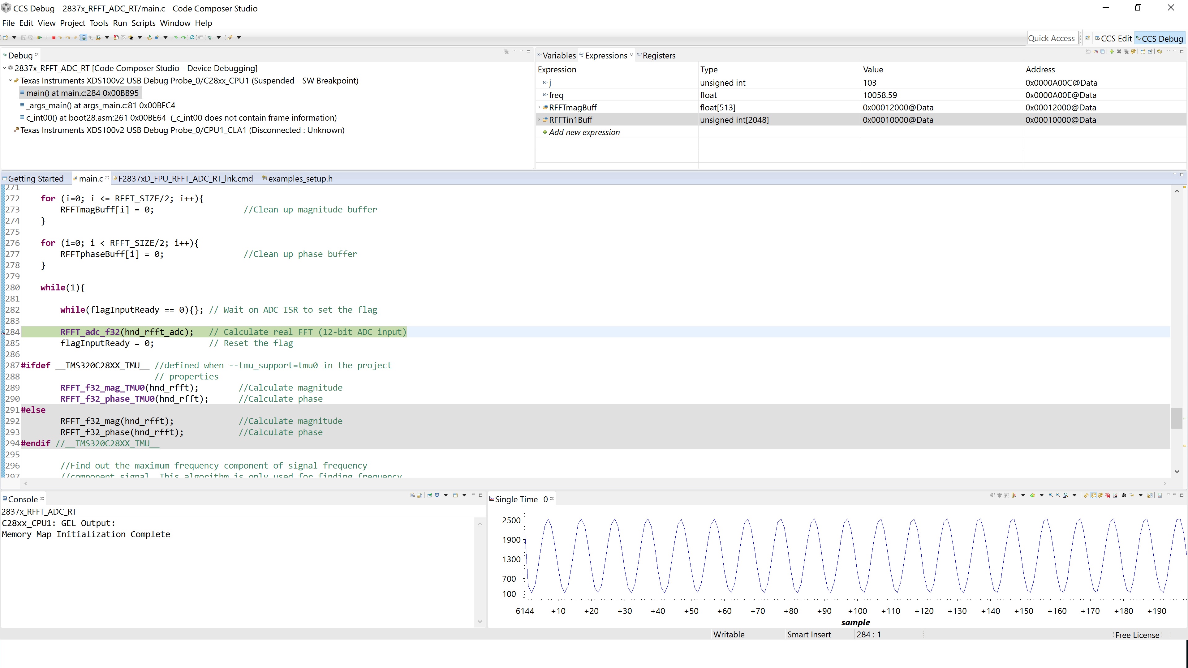
    F_input = 5KHz     freq = 10058.59     j = 103

    ....

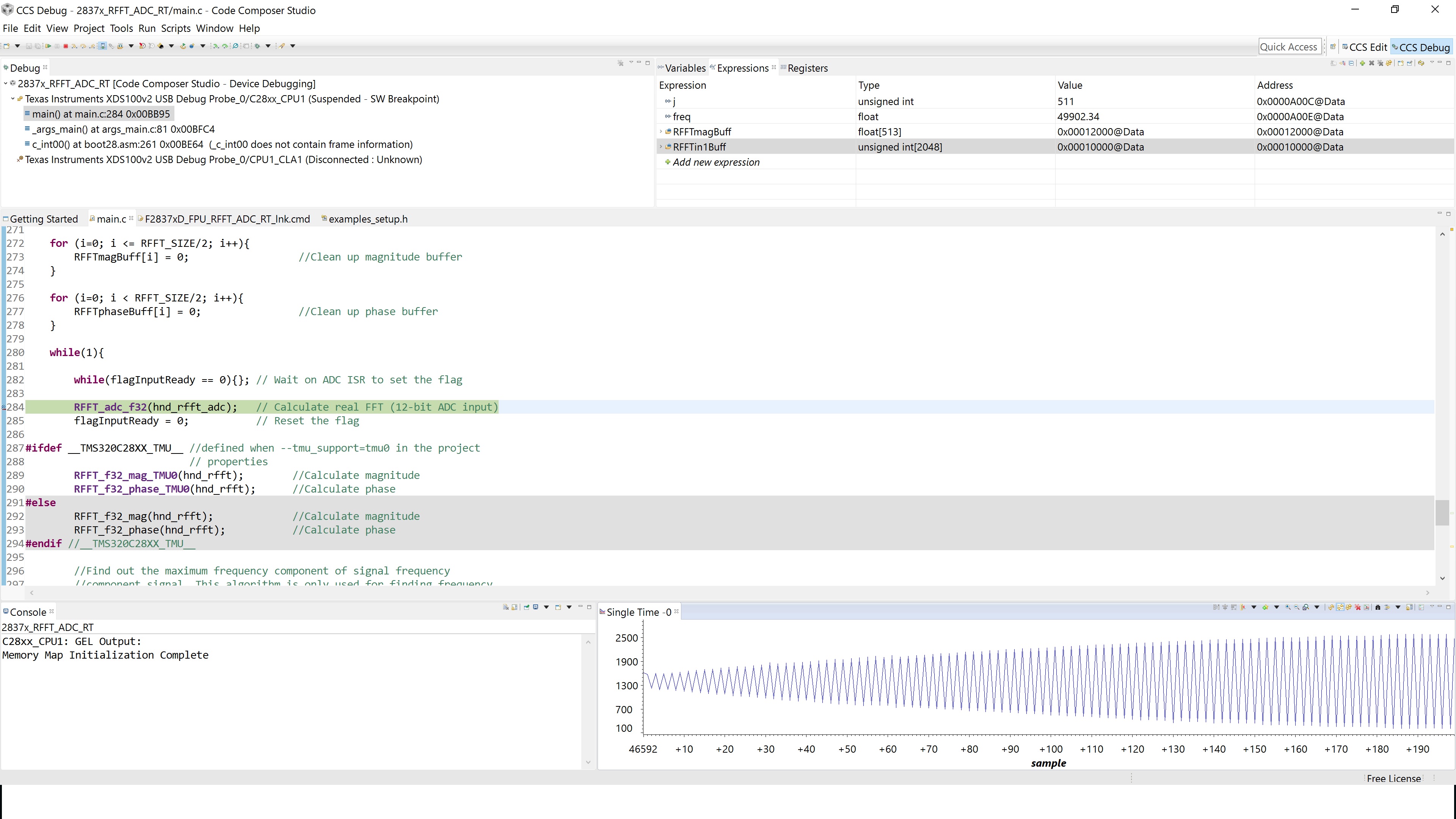
    F_input = 25KHz     freq = 49902.34   j = 511

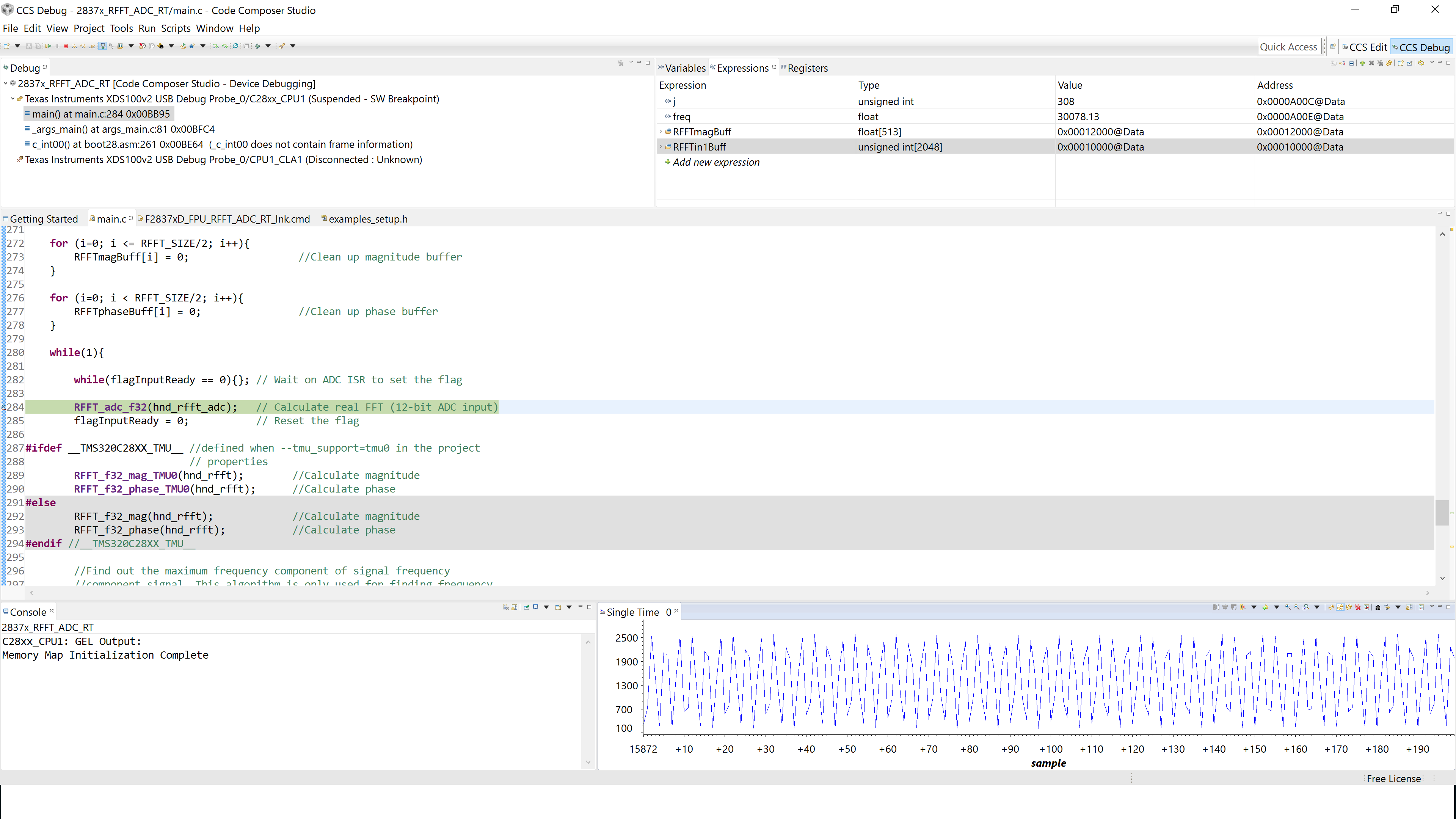
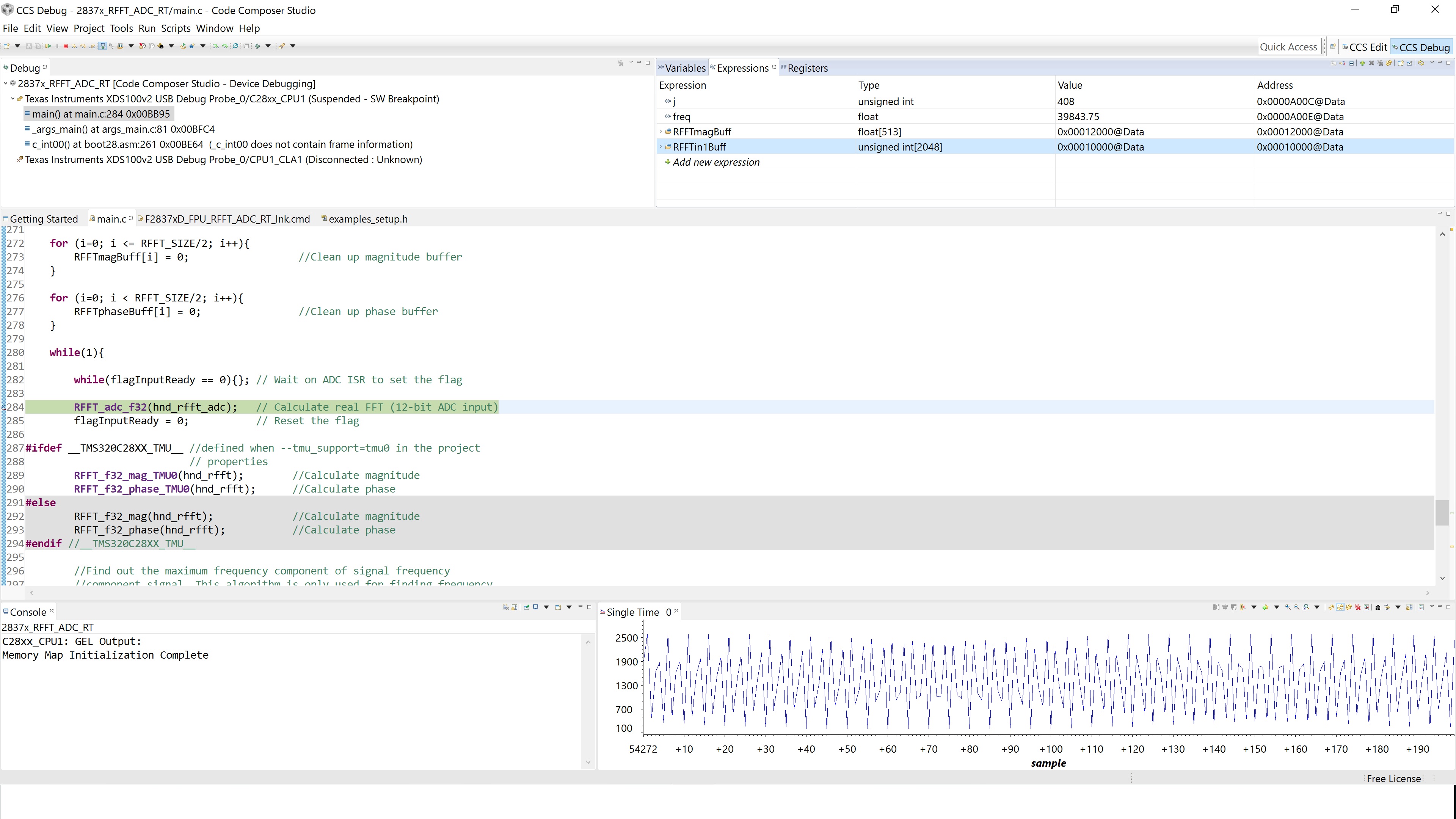
    F_input = 30KHz     freq = 39843.75   j = 408
    F_input = 40KHz   freq = 19824.22     j = 203

    Number of FFT point = 1024
    I do not understand, the "freq"must be at the maximum peak signal.

    Thanks & best regards
    Amin

  • Hi Vishal,
    Why the frequency measurement is incorrect(for 30KHz and more...)?
    Thanks and best regards,
    Amin
  • I wonder if the EPWM that creates the sampling rate is at exactly 100KHz. It looks like its lesser than 100KHz- and you are seeing aliasing for > 30KHz.

    Try to dump the sampling EPWM to an external pin and scope it to see what the actual frequency is.

    The "freq" tries to find the dominant signal in your input. 

  • I also wonder, because according to the Nyquist rate, at the highest level I should be able to measure 40 kHz signal(100KHz/2.5 = 40 KHz), but the result is not correct.

    Input signals generated by the signal generator to ADC PIN_A0.

    Regards,

    Amin

  • Hi Vishal,
    How can I fix this?
    Thank you for your help.
    Best regards,
    Amin
  • You can tell if the sampling frequency is off by observing the input buffer right before the FFT is computed. So if i set a breakpoint at the point of calling the FFT,

        while(1){
            while(flagInputReady == 0){}; // Wait on ADC ISR to set the flag 
                                          // before proceeding
            RFFT_adc_f32(hnd_rfft_adc);   // Calculate real FFT (12-bit ADC input)<-------set breakpoint here
            flagInputReady = 0;           // Reset the flag

    you can observe the sampled waveform in a graph. In CCS, in the debug perspective, go to Tools->Graph->Single Time, Set acquisition buffeer and Data size to 512, data type to unsigned 16 int, and start address to &RFFTin1Buff. Now if you are feeding in a 30KHz sine, and the sampling rate is exactly 100KHz, you should see about 3.3 (100/30) periods of the input. If not it means the sampling rate is off. We need to look at the frequency of EPWM1A ? I think its setup to output on GPIO0 - is it 100KHz?

  • I've used the default program (2837x_rfft_adc_rt), but the number off FFT point is 1024pt,(default: 512pt).

    examples_setup.h
    //*****************************************************************************
    #define CPU_FRQ_200MHZ          1
    #define ADC_SAMPLING_FREQ       100000.0L
    #define EPWM_HSPCLKDIV          1           //EPWM_CLOCK is SYSCLK/(2*2)
    #define EPWM1_PERIOD            500
    #define EPWM1_DUTY_CYCLE        250
    #define EPWM2_PERIOD            50000
    #define EPWM2_DUTY_CYCLE        25000
    
    //*****************************************************************************
    
    
    main.c
    //*****************************************************************************
    #define RFFT_STAGES     10
    #define RFFT_SIZE       (1 << RFFT_STAGES) 
    #define F_PER_SAMPLE    (ADC_SAMPLING_FREQ/(float)RFFT_SIZE)
    #define USE_TEST_INPUT  1 // If not in test mode, be sure to exclude signal.asm
                              // from the build
    #define EPSILON         0.1
    //*****************************************************************************

    Results:

    Input signal: 5KHz


    Input signal: 10KHz

    Input signal: 15KHz


    Input signal: 25KHz


    Input signal: 26KHz


    Input signal: 30KHz

    Thank you for your help.

    Best regards,

    Amin

  • I made a mistake in my earlier post. To figure out how many periods of the input you will capture in the input buffer for a given sampling rate is,

    n_periods = N*(fi/fs) where N is the FFT size, fi the input frequency and fs the sampling frequency.

    So for your case, N = 1024, fs = 100KHz (atleast that is what it should be) and lets take the first input fi = 5KHz

       n_periods  = 1024*(5e3/100e3) = 51.2 periods.

    Now from your first image i count about 20 cycles in the first 196 points in the buffer so if i extend that to the full buffer that is about (20 * (1024/196)) ~ 104.49 periods in the full buffer. It looks like we are not sampling at 100KHz

      fs = N*(fi/n_periods) = 1024*(5e3/104.49) = 49KHZ.

    Im going to assume we are sampling at 50KHz, which explains why everything input beyond 25KHz is wrong.

    There is an issue with the setup of EPWM1A. Let me play around with the example a bit and figure out what the right configuration is.

  • Ok, I think i fixed it

    In examples_setup.h, change the following lines

    #define CPU_FRQ_200MHZ          1
    #define ADC_SAMPLING_FREQ       100000.0L
    #define EPWM_CLK                100000000UL // EPWM_CLK starts off SYSCLK/2
    #define EPWM_CLKDIV             1           // TBCLK = SYSCLK/(2*2)
    #define EPWM_HSPCLKDIV          4           //       = SYSCLK/(2*2*8) or EPWM_CLK/(2*8)
    // desired freq 100KHz
    #define EPWM1_PERIOD            EPWM_CLK/(2*8*100000UL)
    #define EPWM1_DUTY_CYCLE        EPWM1_PERIOD/2UL
    // desired freq 10KHz
    #define EPWM2_PERIOD            (EPWM_CLK)/(2*8*10000UL)
    #define EPWM2_DUTY_CYCLE        EPWM2_PERIOD/2UL

    Then in examples_setup.c add these lines

    void FPU_initEPWM(void)
    {
        CpuSysRegs.PCLKCR2.bit.EPWM1             =1;  // Enable EPWM1 clocks
        CpuSysRegs.PCLKCR2.bit.EPWM2             =1;  // Enable EPWM1 clocks
        
        //Enable EPWM GPIOs
        InitEPwm1Gpio();
        InitEPwm2Gpio();
        
        EALLOW;
        // EPWM clock divider set to /2
        ClkCfgRegs.PERCLKDIVSEL.bit.EPWMCLKDIV = 1;                
        // Turn off the EPWM clock
        CpuSysRegs.PCLKCR0.bit.TBCLKSYNC       = 0;                
        // Disable SOC on A group
        EPwm1Regs.ETSEL.bit.SOCAEN             = 0;                
        // Select SOC on up-count
        EPwm1Regs.ETSEL.bit.SOCASEL            = 4;                
        // Generate pulse on 1st event
        EPwm1Regs.ETPS.bit.SOCAPRD             = 1;                
        // Set compare A value to 2000 counts
        EPwm1Regs.CMPA.bit.CMPA                = EPWM1_DUTY_CYCLE; 
        // Set period to 4000 counts
        EPwm1Regs.TBPRD                        = EPWM1_PERIOD;     
        // freeze counter
        EPwm1Regs.TBCTL.bit.CTRMODE            = 3;                
        //enable SOCA
        EPwm1Regs.ETSEL.bit.SOCAEN             = 1;
        EPwm1Regs.TBCTL.bit.CLKDIV             = EPWM_CLKDIV; //<------- Add line
        EPwm1Regs.TBCTL.bit.HSPCLKDIV          = EPWM_HSPCLKDIV;
        // Disable SOC on A group
        EPwm2Regs.ETSEL.bit.SOCAEN             = 0;                
        // Set compare A value to 10000 counts
        EPwm2Regs.CMPA.bit.CMPA                = EPWM2_DUTY_CYCLE; 
        // Set period to 20000 counts
        EPwm2Regs.TBPRD                        = EPWM2_PERIOD;     
        // freeze counter
        EPwm2Regs.TBCTL.bit.CTRMODE            = 3; 
        EPwm2Regs.TBCTL.bit.CLKDIV             = EPWM_CLKDIV; //<------- Add line
        EPwm2Regs.TBCTL.bit.HSPCLKDIV          = EPWM_HSPCLKDIV;
        // Clear PWM1A on Zero
        EPwm1Regs.AQCTLA.bit.CAU               = AQ_SET;           
        EPwm1Regs.AQCTLA.bit.PRD               = AQ_CLEAR;         
        // Clear PWM2A on Zero
        EPwm2Regs.AQCTLA.bit.CAU               = AQ_SET;           
        EPwm2Regs.AQCTLA.bit.PRD               = AQ_CLEAR;
        
        EDIS;
    }

  • Dear Vishal,

    Thank you for your best help.
    For proposed changes in "examples_setup.h", results are good, for example:
    for maximum 50KHz input signal to ADC pin A0, freq=49609.38 -----> approximately "freq = frequency of input signal" (acceptaple)

    But, when I changed "examples_setup.c" (adding two lines), results are as follows
    for input signal less than 25KHz, like before:
    "freq = 2*frequency of input signal" and results are acceptable.
    for input signal more than 25KHz,
    like before results not acceptable(It's like the ADC sampling rate = 50 kHz).

    ‌Thanks & best regard,
    Amin
  • Dear Vishal,

    How do I fix this problem?

    ‌Thanks & best regard,
    Amin