This thread has been locked.

If you have a related question, please click the "Ask a related question" button in the top right corner. The newly created question will be automatically linked to this question.

TMDSDOCK28379D: pin map and PWM channels

Part Number: TMDSDOCK28379D
Other Parts Discussed in Thread: TMS320F28379D, CONTROLSUITE, TMDSCNCD28379D

Hi,

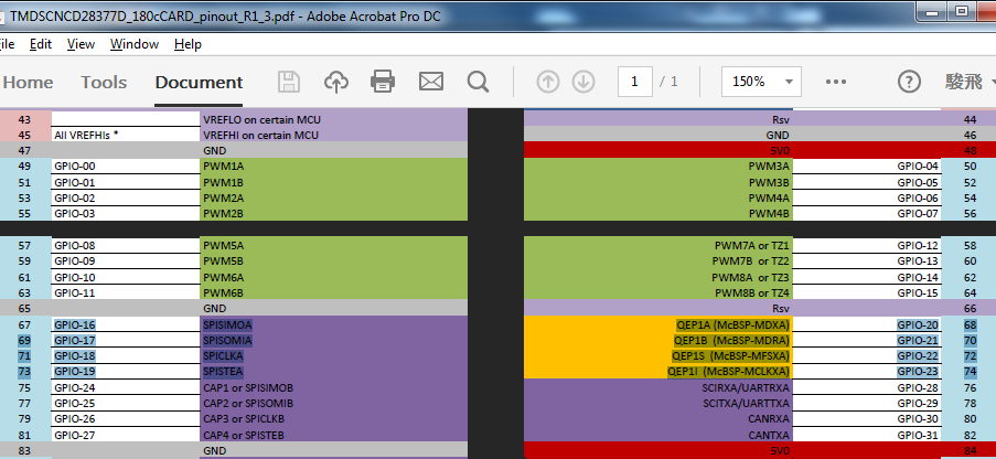
(1) We are trying to do some programming of Delfino TMS320F28379D controlCARD R1.3, and we currently cannot find the pin map. In the control suit folder, we can only find the pin map of 28377D. Could anyone show us the pin map or where to find the pin map?

(2) How many PWM channels can we get access to from Delfino TMS320F28379D controlCARD R1.3? We need all the 24 PWM channels of TMS320F28379D in our application.

Thank you very much!

Sincerely,

Junfei Tang

  • Hi Junfei,

    You can find the documentation in the directory:
    .\controlSUITE\development_kits\~controlCARDs\TMDSCNCD28379D_v1_0\R1_3\

    It looks like you should be able to get all 24 channels out (ePWM1 - ePWM8 are labeled and ePWM9 - ePWM12 can be brought out on GPIO16-GPIO23, which are available).
  • Hi,

    (1) Yes we have found the file. Just for confirmation, we take the pin layout from the 28377D file although we use 28379D, right?

    (2) We are trying connect the TMDSCNCD28379D Experimenter Kit to CCS and build the configuration file. We connected the AJ1 USB port to the computer, but CCS fails to recognize it. Should we connect all the three USB ports (together with the "mini USB port" and the "Power Only J17") to the computer?

    We have configured the switches on the board according to the datasheet.

    Thank you very much!

    Sincerely,

    Junfei Tang

  • Junfei,

    1) Yes, You can use the '377D Schematic, the pinout is the same between the devices.

    2) Which baseboard are you working with?

    • If you have a plain Base station (C:\ti\controlSUITE\development_kits\~ExperimentersKits\120or180pin_HSEC_DockingStn-HWdevPkg_v1_1\R4_1)
      • If you only have the Base station and an external emulator (14-pin JTAG connected to J2, Ensure that A:SW1 position 1 is in the off position. and a mini-USB is plugged in to  J17 for power.
      • If only using USB cables 
        • Power through micro-USB cable in J8 on the controlCard or J17 on Basestation with S1 in the USB-ON positions, and mini-USB to A:J1 on controlCard. Ensure A:SW1 Position 1 is in the ON position
      • Power through 5V barrel Jack (J1  on Basestation). mini-USB to A:J1 on controlCard, with A:SW1 position 1 in the ON position.

    Does this help?

    Thanks,
    Mark

  • Yes, it works. Thank you very much!