This thread has been locked.

If you have a related question, please click the "Ask a related question" button in the top right corner. The newly created question will be automatically linked to this question.

TMS320F28069: XRS in constant reset.

Part Number: TMS320F28069
Other Parts Discussed in Thread: C2000WARE

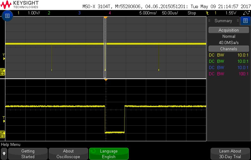
Device is powered correctly with clean 3.3V uses internal 1.8V also very clean yet XRS is issuing a reset every 14mS. Pulse is 50uS wide.  All connections follow datasheet recommendations but because of this the JTAG cannot connect. 

  • Mike,
    please check the device boot mode pins? are they set to wait boot or flash boot? You should be able to connect to JTAG once you set them to WAIT BOOT or SCI BOOT or PARALLEL BOOT.

    Hope this helps.

    Best Regards
    Santosh Athuru
  • Santosh;
    Thanks for the idea I gave it a try but no joy. It doesn’t address the root problem, as I see it. The device is issuing a 50uS reset pulse every 14mS.
  • Mike,

    do you see similar issue on any other chips or just one chip? was this working before? is it a fresh out of factory device or do you have something programmed in it?


    -Santosh Athuru
  • These are fresh from the board house blank devices. This is the very first time I am attempting to power up the boards. I have tested five boards and all act identically. Again the TI part is NOT programmed, never was programmed. This continuous reset is odd as I did follow the datasheet recommendations for decoupling capacitors at each and every pin. The 3.3 V supply is actually 3.451 V, well within the datasheet specification and quite clean. I suspect this is a power issue but can't see where it might come from.
  • Mike,
    I'm looping in few people from team who can suggest you some debug of the power rails. It would help if you can provide the scope captures of the 1.8v, 3.3v and XRSn, for power up and after reset scenarios. Even if the power isn't stable on power up I would assume it to be stable eventually and device should recover at least for debug.

    Looks like in your case the device never recovers?

    Best regards
    Santosh Athuru
  • The XRSn pulsing active at 14 ms is from the watchdog timer (13.11 ms default reset interval from 10 MHz internal oscillator feeding the dog).  This is normal behavior.  If JTAG cannot connect, I would check the JTAG connections and signal integrity on the board.

    Regards,

    David 

  • When the boot mode select pins are set to SCI Boot mode then device shouldn't reset. The ROM code should wait forever waiting for auto baud lock on the SCIA port. Unless something else is going wrong in the device before boot ROM reaches the SCIBOOT function.

    Mike - Can you confirm that the reset pulse is generated when device is set to standalone SCI BOOT?

    Best regards
    Santosh Athuru
  • I would like to attach a pdf of my schematic and bmp of the reset pulse. How do I do that?
  • After you hit the red “Reply” button, click on the blue “Use rich formatting”. You can then use the “paperclip” icon to attach files.


  • I ave attached my schematic in pdf format as well as a bmp of the reset waveform.  Perhaps you can see where I have made my mistake.

     Controller - Project.pdf

  • Mike,

                Had your device been configured to boot to flash, what you are seeing would be normal behavior (as pointed to by David Alter). I see that GPIO34 is connected to GND and GPIO37 goes to the JTAG header. If the emulator is not connected, the internal pull-up for GPIO37 should kick in and put the device in "Wait" mode, in which case you would still see the resets, since WD is enabled in Waitboot(). You can look at the boot-ROM source in  C:\ti\c2000\C2000Ware_1_00_00_00\libraries\boot_rom\f2806x\v1_1\rom_sources\source. Note that even with WAIT BOOT mode, you should be able to connect.


    Did you really intend to connect the boot-mode pins the way you did? The way it is right now, you could only boot to "Wait" mode or the Parallel I/O mode.

  • Mike,    


    Some thoughts:


    Case A: Device has erased flash. Device configured to Boot-to-Flash mode. After reset, CPU tries to “execute” 0xFFFF in flash and takes an ITRAP. ITRAP-ISR enables WD and loops forever. WD counter overflows and resets the device. Cycle repeats all over again.


    Case B: Device has erased flash. Device configured to Wait-boot mode. After reset, CPU executes the WaitBoot() function, which enables WD and loops forever. WD counter overflows and resets the device. Cycle repeats all over again.


    In both cases above, even when the WD is timing out and repeatedly resetting the device, the debugger will still be able to connect to the device. i.e. it can connect in-between the WD resets.


    Could it be that your emulator is defective? If so, it would be unable to establish a connection with the device (and hence take “control” of the CPU and stop it on its tracks and prevent these repeated resets) and we can see these repeated resets.  So, your hardware may be OK, but the emulator could be bad or CCS is not talking to the emulator right. Could you please probe the –TRST pin and see if it toggles when CCS is attempting to make a connection?