This thread has been locked.

If you have a related question, please click the "Ask a related question" button in the top right corner. The newly created question will be automatically linked to this question.

CCS/TMS320F28377D: CAN not working after power reset in 28377D

Part Number: TMS320F28377D
Other Parts Discussed in Thread: CONTROLSUITE, C2000WARE, ISO1050

Tool/software: Code Composer Studio

Hello,

I'm using two custom developed boards having 28377D controller. While working on establishing connection between two controllers(boards) by means of CAN communication, i got this following problem,

in normal condition, when both boards are connected to power supply simulteniously, communication has been done properly. even i checked data on a CAN bus. It was working fine.

But if one of the  board is supplied first, and thenafter  some time delay other board is supplied, CAN communication is not working. 

I have checked initialization portion of the can. I have a doubt in the inter-processor boot mode operation. As in CPU1 software i have given ownwership of CANA module to CPU2. And i have written the whole code of CAN along with initialization of it in CPU2. 

I have checked CANES andCANCTL too. No error flag is high.  auto bus on is kept high. 

After power reset of one of the board, CAN communication is not working. there is no data on a bus. But message RAM interrupt is coming.

If this problem persists, once can is established bewtween two nodes, if i'll add up 3rd node, it will not work for it.

Help me..!!!

  • Hello Meet,

    My setup has up to 8 nodes of 28377D and each node can be powered up independently.  I tried powering up each 28377D with about 5 seconds apart until all 8 nodes are powered up.  CAN communication (transmit/receive) works properly regardless of the power up sequence of the nodes.

    From your description, it seems like your are configuring the CAN modules correctly (absence of error flags).

    Couple of items/questions for you to check:

    - Check if the transceivers are powered up as well when you power up your 28377D boards.

    - What is the CAN clock source that you selected?  Is this clock source stabilized after power up/reset?

    Regards,

    Joseph

  • Thanks for reply Joseph!!

    the checks which u have suggested, after scrutinizing on that i got following.
    1) My both custom boards are same. Both are having same hardware setup, same clock source, same crystal, same power supply IC. Whole configuration is same.

    For testing purpose i have disconnected can cable between two cards, and powered up them simultaneously(both cards have no relavance with eachother as they are completely disconnected for CAN). Now if i connect the cable between two cards,communication works fine.

    now similar test has been done but, powering up two cards at 5 to 10 seconds apart. Then i tried to connect cable, and its not working.

    In one another test i have kept reset button pressed for 2 seconds in both cards untill they get powered up properly(their clock source gets stabalized properly), and then resumed it(not allowing my both DSP to read program for 2 seconds), then also i have observed same phenomenon.If i do power up them simultaneously , CAN communication will work otherwise not.

    And i have used isolated transreceivers. So as u mentioned that if timing of supply generated for transreceiver and DSP chip of perticular card are different, it can create problem. But even if this delay is present than also CAN was working fine when both cards are powered up simultaneously.

    I have done communication between such 16 custom developed cards(16 nodes) having 28335 DSP, in which i have written code by accessing bitfields structures. It is working fine in that setup.

    I'm doubting on API library written for CAN(, as i found that is the only difference between 28377D and 28335 cards.

    Or may be hardware( power supply ) related issue can be there.
    Help me!!
  • Hi Meet,

    From the information you have provided thus far:

      - It looks like SW/CAN API is not an issue:  Your nodes are able to communicate through CAN provided that Power On and Reset are happening at the same time.

      - CAN bus and transceivers do not seem to be an issue:  As long as the 28377D boards/nodes are powered up simultaneously, connecting the CAN bus to the different nodes at different times still allows CAN communication to proceed.

    At this point, I am not saying that the issue is on power supplies/hardware but let us take a look at how you are supplying the different nodes and how the different supply rails for the 28377D are powered up.

      - First question regarding the power supply:  How many rails does your power supply provide?  Is there a separate rail for the 1.2V core and another rail for 3.3V IO, or do you just have one main rail that supplies local LDOs for the individual boards to power up the 1.2V and 3.3V rails that the 28377D requires?  Is there one power supply that provides power to all your nodes and when you say you power the boards up at different times, do you do this through a switch on each board where the main power is coming from one source?

      - Reason for asking these questions is that I want to make sure that you are powering up both 3.3V IO and 1.2V Core supplies at the same time.  If the 1.2V Core powers up first (for instance in your system if the power lines are shared and you have a bigger load/capacitor on the 3.3V rail, this might ramp up later than the 1.2V rail), then we cannot guarantee the proper operation of the device.  Need to make sure that both 1.2V and 3.3V supply rails are powered up at the same time.

      - Lastly, please check if you are using a common ground between the boards that you are connecting.  This is more often overlooked and causes a lot of issues if there is not a common ground connection between the boards.

    Hope these pointers help.  Let me know if you are still having an issue.

    Best regards,

    Joseph


  • Hello Joseph,

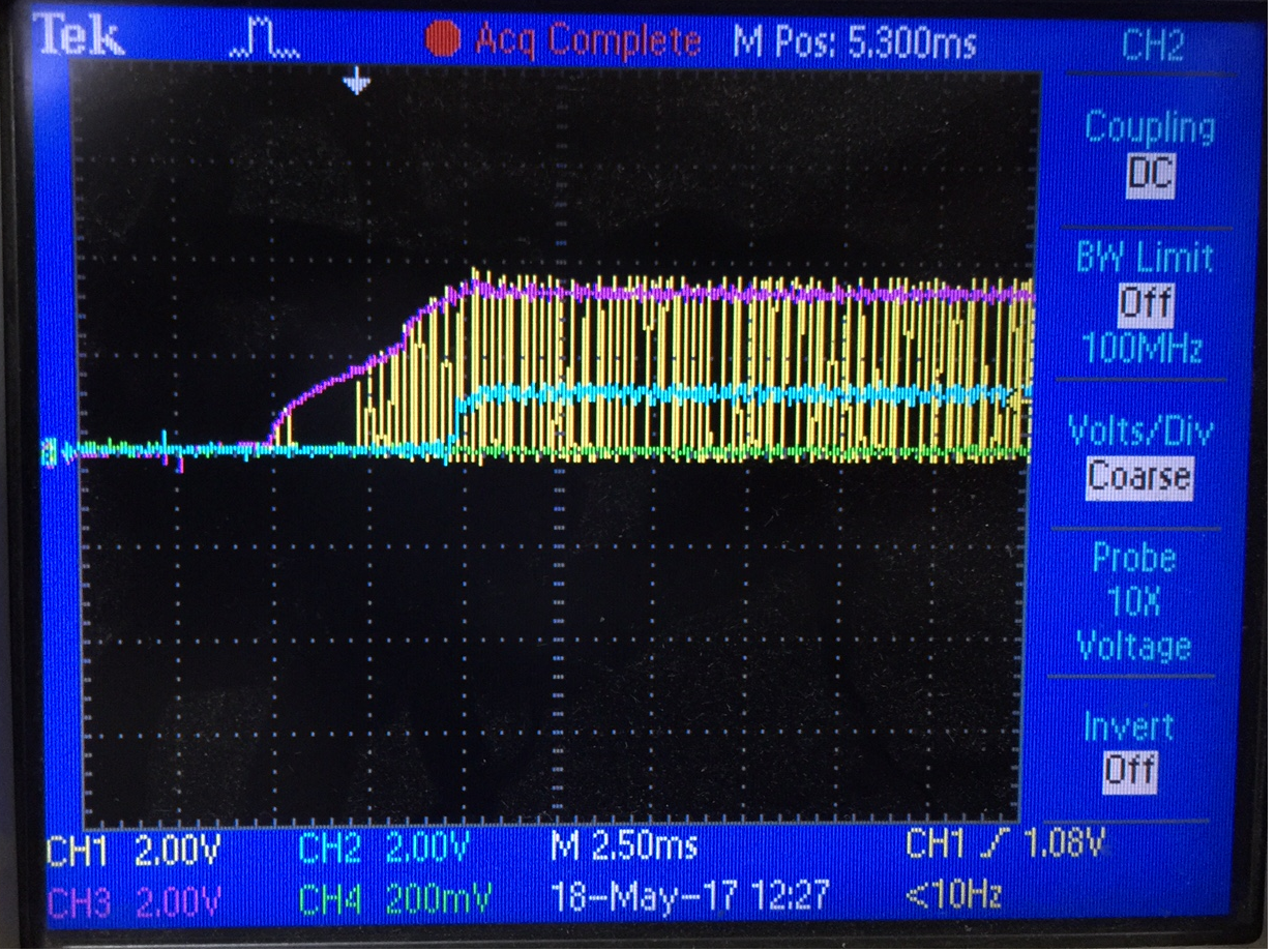
    I took following captures in a scope i have attached it here to let you understand properly.

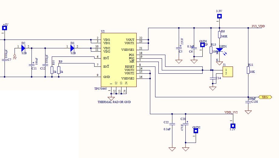
    Basically in power supply section I have one LDO which is TPS70445(having two fixed outputs). Out1 is 3.3V supply for IO and 1.2V is generated for core.

    Further for removal of noise i did put several capacitors for smoothing it up.

    In the place of FB1 and FB4 i have shorted the link(no resistor).

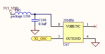
    Now for crystal i took 3.3v supply,

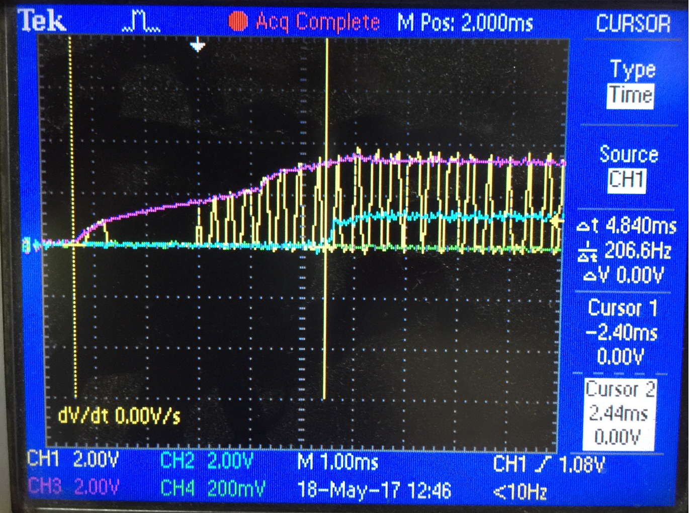
    As u have mentioned that both the supply (core and IO) should turn on simultaneously ( written in a device datasheet too). I have tried to capture the waveforms during the powerup. And i found following results.

    Here channel 1(yello) - clock supply

    channel2(blue) - core supply

    channel3(pink) - IO supply

    And after observing this waveforms i'm doubting my IOsuppy(3.3V) is generated first. Core suppy of 1.2 V is generated after 4.3 msec. So if this delay is causing any issue while configuring CAN we can doubt on Power supply section.

    I have read one application report(SLVA073A) focussing about power supply sequecning of dual supply DSP. in which on page number 5,  they have recommended to power up the core at the same time or before IO for proper peripheral operations.And over here in my results it seems that core is supplied after some time.

    I have disconnected common ground of CAN cable . In a CAN cable m only using CANH and CANL pins hence only 2 wires.

    If this is not the problem then which portion i need to focus on. Please guide me.

    Thanks for your valuable reply Joseph.

    Regards,

    Meet.

  • Hi Meet,

    Thank you for providing more details and taking scope shots of the power rails.  Core and IO supply sequencing seems not to be an issue but I have a question on clock supply.  You indicated that yellow is clock supply, maybe you meant that yellow is the clock source, in this case you are providing 20Mhz source to the 28377D?  If this is indeed the supply line to the clock chip then it is a problem.  Anyway, I am assuming that this is the clock going into your DSP.  While we are at the topic of clock source, I also have a few questions:

        1.) Do you have the parameter of the clock chip, like accuracy and jitter and have you tried scoping the clock source?

        2.) Did you get a chance to measure the clock input to the DSP individually when both nodes are powered up simultaneously and when one node is powered up after the other?

        3.) When setting up the CAN module, what is the clock source selected?  (i.e. - when using C2000Ware or ControlSUITE CAN routines, this is the CANClkSourceSelect function).  Is it from X1 input or SYSCLK?

    Lastly, do you have an access to a CAN interface (example: National Instruments 8473 or similar) that you can connect to a PC so you can monitor activities on the CAN bus?  This would be a valuable tool that would help you monitor the CAN bus activity and can simplify debug process.

    Thanks,

    Joseph

  • Hello Joseph,
    Finally my problem got resolved. Actually it was problem related to hardware only. I have made isolated supply of 3.3V for CAN transreciever . It should be between 4.75 to 5.5 V for proper operation. I removed LDO and connected 5V directly to secondary side (bus Side) supply of ISO1050 CAN transreciever. And it is working fine even after power reset of my DSP.

    Thank you for your valuable replies Joseph.
    I would like to be in connection with you further. Reuesting you to share your EMAIL ID.

    Regards,
    Meet.
  • Hello Meet,

    Sorry for the late response.  Good to know that you have finally resolved your issue.  I did not think about that, but the symptoms you described is consistent with incorrect supply rail for your IO transceiver.

    Unfortunately, it is our company policy to not share our email ID in the forum.  We have moderators who monitor all the posts and assign them per each area of expertise, this way the E2E community can benefit from the responses and experiences from the community members.  Our responsibilities sometimes do change hence use of email to communicate issues in the forum is discouraged.  Please continue using the forum as a means to communicate your issues with our products.  Rest assured, our moderators will try their best to assign resources to answer whatever queries you may have.

    Regards,

    Joseph