This thread has been locked.

If you have a related question, please click the "Ask a related question" button in the top right corner. The newly created question will be automatically linked to this question.

CCS/LAUNCHXL-F28377S: Could you suggest me how to use ADC in LAUNCHXL-F28377S

Part Number: LAUNCHXL-F28377S
Other Parts Discussed in Thread: CONTROLSUITE, C2000WARE, LAUNCHXL-F28379D

Tool/software: Code Composer Studio

Hello everyone,

I have 1 current sensor that release AC voltage and I want to read them by using LAUNCHXL-F28377S.
Could you suggest me what code that I have to use and how to connect it with LAUNCHXL-F28377S.

Thank you in advance.

kanthanet 

  • Hi Kanthanet,

    You can find some ADC example SW to get you up and running in ControlSUITE or C2000 ware.  

    As far as interfacing to your sensor, that is a pretty broad question.  At a very high level you will want to get the output of your sensor in the range of 0 to VREFHI and you want to drive the ADC with a sufficiently low impedance source such that it can achieve good input settling for your given S+H duration requirements and/or sample rate requirements. 

  • Thank you for answering my question,

    but I still don't understand some word of your sentence such as S+H duration , VREFHI so,
    Can you give me some document of them and I will read it.

    I am the beginner one so, please forgive me if I make you get annoying.
    kanthanet
  • Hi Kanthanet,

    Firstly, download datasheet and the TRM for the above device from the Device Homepage. In the TRM, you'll be able to find ADC peripheral Section that you can go through. As for sample codes once you download C2000ware you can navigate to this folder:

    C:\ti\c2000\C2000Ware_1_00_00_00\device_support\f2837xs\examples\cpu1\adc_soc_epwm

    Regards,
    Gautam
  • I did it already.
    I connect the output of my sensor to J3:27 as following the source code but it didn't work.
    It said "asm(" ESTOP0");"

    Can you suggest me please?
    p.s. my current sensor has 3 wires that contain VDD=5V, GND, and output signal.

    thank you in advance.
  • Can you share the screenshot?
  • Dear Gautam,

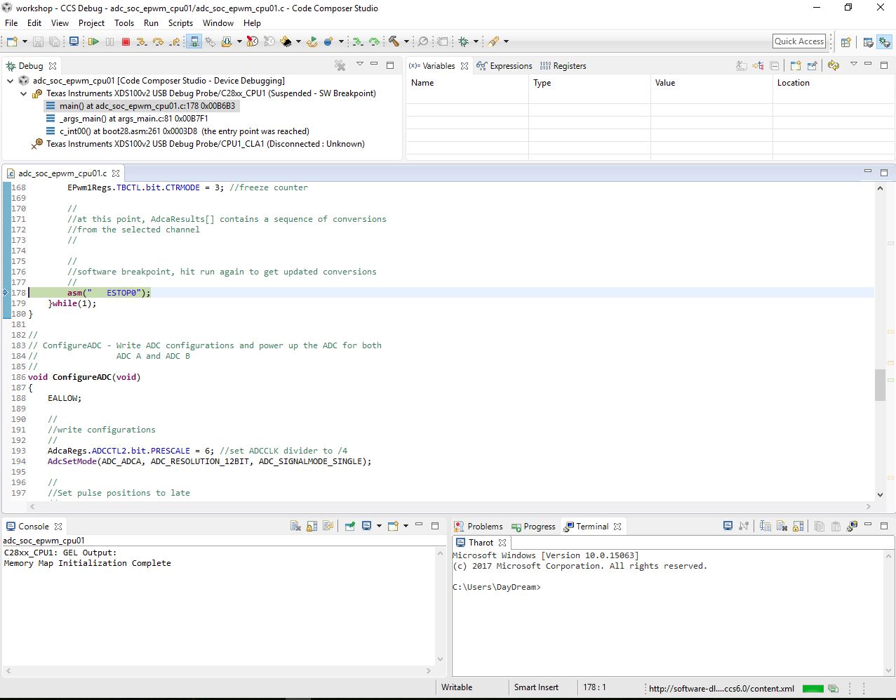
    This is my error as the screenshot below:

    and I used this source code:

    //###########################################################################
    //
    // FILE:   adc_soc_epwm_cpu01.c
    //
    // TITLE:  ADC triggering via epwm for F2837xS.
    //
    //! \addtogroup cpu01_example_list
    //! <h1> ADC ePWM Triggering (adc_soc_epwm)</h1>
    //!
    //! This example sets up the ePWM to periodically trigger the ADC.
    //!
    //! After the program runs, the memory will contain:\n
    //! - \b AdcaResults \b: A sequence of analog-to-digital conversion samples from
    //! pin A0. The time between samples is determined based on the period
    //! of the ePWM timer.
    //
    //###########################################################################
    // $TI Release: F2837xS Support Library v200 $
    // $Release Date: Tue Jun 21 13:52:16 CDT 2016 $
    // $Copyright: Copyright (C) 2014-2016 Texas Instruments Incorporated -
    //             http://www.ti.com/ ALL RIGHTS RESERVED $
    //###########################################################################
    
    //
    // Included Files
    //
    #include "F28x_Project.h"
    
    //
    // Function Prototypes
    //
    void ConfigureADC(void);
    void ConfigureEPWM(void);
    void SetupADCEpwm(Uint16 channel);
    interrupt void adca1_isr(void);
    
    //
    // Defines
    //
    #define RESULTS_BUFFER_SIZE 256
    
    //
    // Globals
    //
    Uint16 AdcaResults[RESULTS_BUFFER_SIZE];
    Uint16 resultsIndex;
    volatile Uint16 bufferFull;
    
    void main(void)
    {
    //
    // Step 1. Initialize System Control:
    // PLL, WatchDog, enable Peripheral Clocks
    // This example function is found in the F2837xS_SysCtrl.c file.
    //
        InitSysCtrl();
    
    //
    // Step 2. Initialize GPIO:
    // This example function is found in the F2837xS_Gpio.c file and
    // illustrates how to set the GPIO to it's default state.
    //
        InitGpio(); // Skipped for this example
    
    //
    // Step 3. Clear all interrupts and initialize PIE vector table:
    // Disable CPU interrupts
    //
        DINT;
    
    //
    // Initialize the PIE control registers to their default state.
    // The default state is all PIE interrupts disabled and flags
    // are cleared.
    // This function is found in the F2837xS_PieCtrl.c file.
    //
        InitPieCtrl();
    
    //
    // Disable CPU interrupts and clear all CPU interrupt flags:
    //
        IER = 0x0000;
        IFR = 0x0000;
    
    //
    // Initialize the PIE vector table with pointers to the shell Interrupt
    // Service Routines (ISR).
    // This will populate the entire table, even if the interrupt
    // is not used in this example.  This is useful for debug purposes.
    // The shell ISR routines are found in F2837xS_DefaultIsr.c.
    // This function is found in F2837xS_PieVect.c.
    //
        InitPieVectTable();
    
    //
    // Map ISR functions
    //
        EALLOW;
        PieVectTable.ADCA1_INT = &adca1_isr; //function for ADCA interrupt 1
        EDIS;
    
    //
    // Configure the ADC and power it up
    //
        ConfigureADC();
    
    //
    // Configure the ePWM
    //
        ConfigureEPWM();
    
    //
    // Setup the ADC for ePWM triggered conversions on channel 0
    //
        SetupADCEpwm(0);
    
    //
    // Enable global Interrupts and higher priority real-time debug events:
    //
        IER |= M_INT1; //Enable group 1 interrupts
        EINT;  // Enable Global interrupt INTM
        ERTM;  // Enable Global realtime interrupt DBGM
    
    //
    // Initialize results buffer
    //
        for(resultsIndex = 0; resultsIndex < RESULTS_BUFFER_SIZE; resultsIndex++)
        {
            AdcaResults[resultsIndex] = 0;
        }
        resultsIndex = 0;
        bufferFull = 0;
    
    //
    // enable PIE interrupt
    //
        PieCtrlRegs.PIEIER1.bit.INTx1 = 1;
    
    //
    // sync ePWM
    //
        EALLOW;
        CpuSysRegs.PCLKCR0.bit.TBCLKSYNC = 1;
    
    //
    //take conversions indefinitely in loop
    //
        do
        {
            //
            //start ePWM
            //
            EPwm1Regs.ETSEL.bit.SOCAEN = 1;  //enable SOCA
            EPwm1Regs.TBCTL.bit.CTRMODE = 0; //unfreeze, and enter up count mode
    
            //
            //wait while ePWM causes ADC conversions, which then cause interrupts,
            //which fill the results buffer, eventually setting the bufferFull
            //flag
            //
            while(!bufferFull);
            bufferFull = 0; //clear the buffer full flag
    
            //
            //stop ePWM
            //
            EPwm1Regs.ETSEL.bit.SOCAEN = 0;  //disable SOCA
            EPwm1Regs.TBCTL.bit.CTRMODE = 3; //freeze counter
    
            //
            //at this point, AdcaResults[] contains a sequence of conversions
            //from the selected channel
            //
    
            //
            //software breakpoint, hit run again to get updated conversions
            //
            asm("   ESTOP0");
        }while(1);
    }
    
    //
    // ConfigureADC - Write ADC configurations and power up the ADC for both
    //                ADC A and ADC B
    //
    void ConfigureADC(void)
    {
        EALLOW;
    
        //
        //write configurations
        //
        AdcaRegs.ADCCTL2.bit.PRESCALE = 6; //set ADCCLK divider to /4
        AdcSetMode(ADC_ADCA, ADC_RESOLUTION_12BIT, ADC_SIGNALMODE_SINGLE);
    
        //
        //Set pulse positions to late
        //
        AdcaRegs.ADCCTL1.bit.INTPULSEPOS = 1;
    
        //
        //power up the ADC
        //
        AdcaRegs.ADCCTL1.bit.ADCPWDNZ = 1;
    
        //
        //delay for 1ms to allow ADC time to power up
        //
        DELAY_US(1000);
    
        EDIS;
    }
    
    //
    // ConfigureEPWM - Configure EPWM SOC and compare values
    //
    void ConfigureEPWM(void)
    {
        EALLOW;
        // Assumes ePWM clock is already enabled
        EPwm1Regs.ETSEL.bit.SOCAEN    = 0;    // Disable SOC on A group
        EPwm1Regs.ETSEL.bit.SOCASEL    = 4;   // Select SOC on up-count
        EPwm1Regs.ETPS.bit.SOCAPRD = 1;       // Generate pulse on 1st event
        EPwm1Regs.CMPA.bit.CMPA = 0x0800;     // Set compare A value to 2048 counts
        EPwm1Regs.TBPRD = 0x1000;             // Set period to 4096 counts
        EPwm1Regs.TBCTL.bit.CTRMODE = 3;      // freeze counter
        EDIS;
    }
    
    //
    // SetupADCEpwm - Setup ADC EPWM acquisition window
    //
    void SetupADCEpwm(Uint16 channel)
    {
        Uint16 acqps;
    
        //
        //determine minimum acquisition window (in SYSCLKS) based on resolution
        //
        if(ADC_RESOLUTION_12BIT == AdcaRegs.ADCCTL2.bit.RESOLUTION)
        {
            acqps = 14; //75ns
        }
        else //resolution is 16-bit
        {
            acqps = 63; //320ns
        }
    
        //
        //Select the channels to convert and end of conversion flag
        //
        EALLOW;
        AdcaRegs.ADCSOC0CTL.bit.CHSEL = channel;  //SOC0 will convert pin A0
        AdcaRegs.ADCSOC0CTL.bit.ACQPS = acqps; //sample window is 100 SYSCLK cycles
        AdcaRegs.ADCSOC0CTL.bit.TRIGSEL = 5; //trigger on ePWM1 SOCA/C
        AdcaRegs.ADCINTSEL1N2.bit.INT1SEL = 0; //end of SOC0 will set INT1 flag
        AdcaRegs.ADCINTSEL1N2.bit.INT1E = 1;   //enable INT1 flag
        AdcaRegs.ADCINTFLGCLR.bit.ADCINT1 = 1; //make sure INT1 flag is cleared
        EDIS;
    }
    
    //
    // adca1_isr - Read ADC Buffer in ISR
    //
    interrupt void adca1_isr(void)
    {
        AdcaResults[resultsIndex++] = AdcaResultRegs.ADCRESULT0;
        if(RESULTS_BUFFER_SIZE <= resultsIndex)
        {
            resultsIndex = 0;
            bufferFull = 1;
        }
    
        AdcaRegs.ADCINTFLGCLR.bit.ADCINT1 = 1; //clear INT1 flag
        PieCtrlRegs.PIEACK.all = PIEACK_GROUP1;
    }
    
    //
    // End of file
    //
    

  • //###########################################################################
    //
    // FILE: adc_soc_epwm_cpu01.c
    //
    // TITLE: ADC triggering via epwm for F2837xS.
    //
    //! \addtogroup cpu01_example_list
    //! <h1> ADC ePWM Triggering (adc_soc_epwm)</h1>
    //!
    //! This example sets up the ePWM to periodically trigger the ADC.
    //!
    //! After the program runs, the memory will contain:\n
    //! - \b AdcaResults \b: A sequence of analog-to-digital conversion samples from
    //! pin A0. The time between samples is determined based on the period
    //! of the ePWM timer.
    //
    //###########################################################################
    // $TI Release: F2837xS Support Library v200 $
    // $Release Date: Tue Jun 21 13:52:16 CDT 2016 $
    // $Copyright: Copyright (C) 2014-2016 Texas Instruments Incorporated -
    // http://www.ti.com/ ALL RIGHTS RESERVED $
    //###########################################################################

    //
    // Included Files
    //
    #include "F28x_Project.h"

    //
    // Function Prototypes
    //
    void ConfigureADC(void);
    void ConfigureEPWM(void);
    void SetupADCEpwm(Uint16 channel);
    interrupt void adca1_isr(void);

    //
    // Defines
    //
    #define RESULTS_BUFFER_SIZE 256

    //
    // Globals
    //
    Uint16 AdcaResults[RESULTS_BUFFER_SIZE];
    Uint16 resultsIndex;
    volatile Uint16 bufferFull;

    void main(void)
    {
    //
    // Step 1. Initialize System Control:
    // PLL, WatchDog, enable Peripheral Clocks
    // This example function is found in the F2837xS_SysCtrl.c file.
    //
    InitSysCtrl();

    //
    // Step 2. Initialize GPIO:
    // This example function is found in the F2837xS_Gpio.c file and
    // illustrates how to set the GPIO to it's default state.
    //
    InitGpio(); // Skipped for this example

    //
    // Step 3. Clear all interrupts and initialize PIE vector table:
    // Disable CPU interrupts
    //
    DINT;

    //
    // Initialize the PIE control registers to their default state.
    // The default state is all PIE interrupts disabled and flags
    // are cleared.
    // This function is found in the F2837xS_PieCtrl.c file.
    //
    InitPieCtrl();

    //
    // Disable CPU interrupts and clear all CPU interrupt flags:
    //
    IER = 0x0000;
    IFR = 0x0000;

    //
    // Initialize the PIE vector table with pointers to the shell Interrupt
    // Service Routines (ISR).
    // This will populate the entire table, even if the interrupt
    // is not used in this example. This is useful for debug purposes.
    // The shell ISR routines are found in F2837xS_DefaultIsr.c.
    // This function is found in F2837xS_PieVect.c.
    //
    InitPieVectTable();

    //
    // Map ISR functions
    //
    EALLOW;
    PieVectTable.ADCA1_INT = &adca1_isr; //function for ADCA interrupt 1
    EDIS;

    //
    // Configure the ADC and power it up
    //
    ConfigureADC();

    //
    // Configure the ePWM
    //
    ConfigureEPWM();

    //
    // Setup the ADC for ePWM triggered conversions on channel 0
    //
    SetupADCEpwm(0);

    //
    // Enable global Interrupts and higher priority real-time debug events:
    //
    IER |= M_INT1; //Enable group 1 interrupts
    EINT; // Enable Global interrupt INTM
    ERTM; // Enable Global realtime interrupt DBGM

    //
    // Initialize results buffer
    //
    for(resultsIndex = 0; resultsIndex < RESULTS_BUFFER_SIZE; resultsIndex++)
    {
    AdcaResults[resultsIndex] = 0;
    }
    resultsIndex = 0;
    bufferFull = 0;

    //
    // enable PIE interrupt
    //
    PieCtrlRegs.PIEIER1.bit.INTx1 = 1;

    //
    // sync ePWM
    //
    EALLOW;
    CpuSysRegs.PCLKCR0.bit.TBCLKSYNC = 1;

    //
    //take conversions indefinitely in loop
    //
    do
    {
    //
    //start ePWM
    //
    EPwm1Regs.ETSEL.bit.SOCAEN = 1; //enable SOCA
    EPwm1Regs.TBCTL.bit.CTRMODE = 0; //unfreeze, and enter up count mode

    //
    //wait while ePWM causes ADC conversions, which then cause interrupts,
    //which fill the results buffer, eventually setting the bufferFull
    //flag
    //
    while(!bufferFull);
    bufferFull = 0; //clear the buffer full flag

    //
    //stop ePWM
    //
    EPwm1Regs.ETSEL.bit.SOCAEN = 0; //disable SOCA
    EPwm1Regs.TBCTL.bit.CTRMODE = 3; //freeze counter

    //
    //at this point, AdcaResults[] contains a sequence of conversions
    //from the selected channel
    //

    //
    //software breakpoint, hit run again to get updated conversions
    //
    asm(" ESTOP0");
    }while(1);
    }

    //
    // ConfigureADC - Write ADC configurations and power up the ADC for both
    // ADC A and ADC B
    //
    void ConfigureADC(void)
    {
    EALLOW;

    //
    //write configurations
    //
    AdcaRegs.ADCCTL2.bit.PRESCALE = 6; //set ADCCLK divider to /4
    AdcSetMode(ADC_ADCA, ADC_RESOLUTION_12BIT, ADC_SIGNALMODE_SINGLE);

    //
    //Set pulse positions to late
    //
    AdcaRegs.ADCCTL1.bit.INTPULSEPOS = 1;

    //
    //power up the ADC
    //
    AdcaRegs.ADCCTL1.bit.ADCPWDNZ = 1;

    //
    //delay for 1ms to allow ADC time to power up
    //
    DELAY_US(1000);

    EDIS;
    }

    //
    // ConfigureEPWM - Configure EPWM SOC and compare values
    //
    void ConfigureEPWM(void)
    {
    EALLOW;
    // Assumes ePWM clock is already enabled
    EPwm1Regs.ETSEL.bit.SOCAEN = 0; // Disable SOC on A group
    EPwm1Regs.ETSEL.bit.SOCASEL = 4; // Select SOC on up-count
    EPwm1Regs.ETPS.bit.SOCAPRD = 1; // Generate pulse on 1st event
    EPwm1Regs.CMPA.bit.CMPA = 0x0800; // Set compare A value to 2048 counts
    EPwm1Regs.TBPRD = 0x1000; // Set period to 4096 counts
    EPwm1Regs.TBCTL.bit.CTRMODE = 3; // freeze counter
    EDIS;
    }

    //
    // SetupADCEpwm - Setup ADC EPWM acquisition window
    //
    void SetupADCEpwm(Uint16 channel)
    {
    Uint16 acqps;

    //
    //determine minimum acquisition window (in SYSCLKS) based on resolution
    //
    if(ADC_RESOLUTION_12BIT == AdcaRegs.ADCCTL2.bit.RESOLUTION)
    {
    acqps = 14; //75ns
    }
    else //resolution is 16-bit
    {
    acqps = 63; //320ns
    }

    //
    //Select the channels to convert and end of conversion flag
    //
    EALLOW;
    AdcaRegs.ADCSOC0CTL.bit.CHSEL = channel; //SOC0 will convert pin A0
    AdcaRegs.ADCSOC0CTL.bit.ACQPS = acqps; //sample window is 100 SYSCLK cycles
    AdcaRegs.ADCSOC0CTL.bit.TRIGSEL = 5; //trigger on ePWM1 SOCA/C
    AdcaRegs.ADCINTSEL1N2.bit.INT1SEL = 0; //end of SOC0 will set INT1 flag
    AdcaRegs.ADCINTSEL1N2.bit.INT1E = 1; //enable INT1 flag
    AdcaRegs.ADCINTFLGCLR.bit.ADCINT1 = 1; //make sure INT1 flag is cleared
    EDIS;
    }

    //
    // adca1_isr - Read ADC Buffer in ISR
    //
    interrupt void adca1_isr(void)
    {
    AdcaResults[resultsIndex++] = AdcaResultRegs.ADCRESULT0;
    if(RESULTS_BUFFER_SIZE <= resultsIndex)
    {
    resultsIndex = 0;
    bufferFull = 1;
    }

    AdcaRegs.ADCINTFLGCLR.bit.ADCINT1 = 1; //clear INT1 flag
    PieCtrlRegs.PIEACK.all = PIEACK_GROUP1;
    }

    //
    // End of file
    //
  • or I have to set the pin for read ADC?

  • Hi Kanthanet,

    For your question a few posts up:

    When the program reaches ESTOP, it has essentially finished running; this is the intended operation, not an error. You can then examine the contents of AdcaResults[] or the ADC HW result registers directly.
  • Dear Devin,

    Thank you so much.
    and where is the A0 pin because I am trying to connect with pin J3:27 refer to ADCINA0 from the datasheet.
    Moreover, can you suggest me to set the pin to receive ADC signal from the my code above.

    Thank you in advance,
    kanthanet
  • Hi kanthanet,

    You can find the Launchpad schematics in ControlSUITE in \controlSUITE\development_kits\LAUNCHXL-F28377S\HwDevPkg\.

    If you search the PDF for ADCINA0 you can find where it is physically located. I think you have correctly identified that it is connected to J3.

    To change the sampled channel you change the CHSEL setting in the SOC configurations.
  • Now, I can see the value from my current sensor but, 
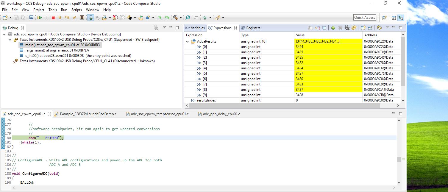
    it has some problem cauesd the value that I got it wasn't the same when I measured by using multimeter like this picture below:

    Actually, it should be 2500 and how to change int to float?

    Thank you in advance,

    kanthanet

  • Hi Kanthanet,

    What is the VREFHI range and what is the input voltage?  What is the impedance of your sensor / input source vs. what is the S+H duration for your sample?

    To get into float, I think you want to cast the raw conversion result to float, then calculate

    result (float, in volts) = VREFH (float, in volts) * result (int, in LSBs) / 4096

  • -my VREFHI range is 0-5V,
    -what is the S+H duration for your sample?
    ans. I am not sure how to fing this but, from the datasheet that said "The conversion time is approximately 10.5 ADCCLK
    cycles in 12-bit mode and 29.5 ADCCLK cycles in 16-bit mode."
    So, my S+H duration is 12 bit (10.5 ADCCLK)
    -What is the impedance of your sensor / input source?
    ans. I don't know
    -What is LSBs?

    this is my current sensor datasheet below?


    MLX91207-DVK.pdf

    Thank you in advance,

    kanthanet

  • Hi Kanthanet,

    The VREFHI can not exceed VDDA on this device, so your ADC reference range I don't think can be 0 to 5V. Usually this is 0 to 3.0V or 0 to 2.5V. You can check the launchpad schematic and/or measure the voltage on the VREFHI pin on the launchpad.

    The S+H duration is controlled by the ACQPS setting of the SOC. The S+H duration is (ACQPS + 1)*SYSCLKs. If the device is operating at 200MHz 1 SYSCLK will be 5ns. The minimum S+H duration (75ns) will only be good if you are driving with a low impedance + high bandwidth source: usually this would be if you are directly driving the pin with an op-amp. Otherwise, you need to adjust the S+H duration to be longer based on the impedance of your sensor (high impedance requires longer S+H duration).

    An LSB is (VREFHI - VREFLO) / 2^N, where N is the number of bits in the ADC. Since VREFLO = 0 and N = 12, one LSB is VREFHI / 4096. With a 3.0V reference this would be 732uV. When the ADC produces a digital output, the reading is in LSBs between 0 and 4095.
  • I do not think the Launchpad A/D likes negative voltages or voltages above VRefHi.

    I've seen 5 Volts to a digital I/O fry a F28069 part.

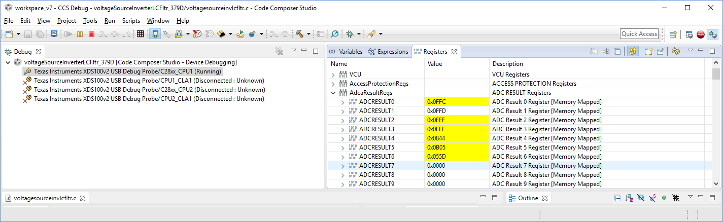
    The values in your adaResultsReg look suspicious. They are all very close to one another.

    Here is a snapshot of my board. LaunchXL-F28379D

  • Confirmed: applying 5V to any pin will almost certainly damage the part.

    To avoid damage you should not apply any voltage less than -0.3V to any analog or digital pin and nothing above VDDA + 0.3V (analog pins) or VDDIO + 0.3V (digital pins).

    For most digital IO and ADC input pins, if you provide a current-limiting resistor you can instead worry about the clamping current into the pin. Current should be limited to +/-2mA (continuous) and no more than +/-20mA total instantaneous current between all pins.
  • Hi Devin,

    Now, I know the VREFHI is 3.0V
    and then how to mix "result (float, in volts) = VREFH (float, in volts) * result (int, in LSBs) / 4096"
    with my code.
    I tried many times already and, it wasn't work at all.
    Could you please suggest me?

    Thank you in advance,
    kanthanet
  • Hi Kanthanet,

      I'm guessing you are doing a power supply.  If it is a buck power supply, you might want to import the project

    C:\ti\controlSUITE\development_kits\BOOSTXL_BUCKCONV\v1_01_00_00\Buck_VMC_F2837xS

    It has some of the A/D's already set up and you can see a response like you have shown you already know how to do.

    -Regards

  • c=(float)3.0/4096;
    tension=(float)(3.0/4096)*AdcaResult0;

    something like this ?

    Thank you in advance,
    kanthanet
  • Thank you so much, ProgrammableSolution.
    Actually I didn't doing a power supply but, thank you for helping me.

    Regards,
    kanthanet
  • Your welcome.

    In the Buck_VMC-Main.c file, they do macros like
    #define Vout1R AdcaResultRegs.ADCRESULT0 //
    ----------------------
    I then use this like
    volatile Uint16 Vout1R_A;

    if(gpio69_val == 0)
    Vout1R_A = Vout1R;
    else
    Vout1R_A = rdata_a;

    Good Luck!