Because of the holidays, TI E2E™ design support forum responses will be delayed from Dec. 25 through Jan. 2. Thank you for your patience.

This thread has been locked.

If you have a related question, please click the "Ask a related question" button in the top right corner. The newly created question will be automatically linked to this question.

CCS/TMS320F28027: TMS320F28027

Part Number: TMS320F28027
Other Parts Discussed in Thread: CONTROLSUITE, LAUNCHXL-F28027,

Tool/software: Code Composer Studio

Hi all,

I am trying to flash program TI 28027 using Black Hawk USB2000 controller. The TMS 28027 was soldered onto a breakout board. The following connections were done

(TRST,TMS,TCK,TDI,TDO,XRS), VDD and VSS. I have not connected external oscillator. The VREG has been grounded.  I am using the flash program example available in control suite. However, I am getting the following errror.

C28xx: Failed CPU Reset: (Error -1156 @ 0x6) Device may be operating in low-power mode. Do you want to bring it out of this mode? (Emulation package 6.0.83.0)

I have two queries:

a) what is the reason for this error. Any specific connections that may have been left out.

b)What are the necessary connections to flash program 28027 using Black Hawk USB 2000 controller. Any references for the procedure and connections to be done.


Thanking you

  • Hi Sachin,

    Did you refer F28027 launchpad schematics for basic connections?

    BTW is this issue similar to your previous post?

    Regards,
    Gautam

  • Hi Gautam,

    I have connected XRS pin to Vdd via 2.2k resistor as you mentioned on my earlier post.

    Yes this post is related to earlier post. As I was not getting reply in that, I made a new post. I used connection scheme as given in application note" 800VA Pure Sine Wave Inverter’s Reference Design(SLAA602) pg 21" and made connection pins available for programming through USB2000 black hawk. Thanks.
  • Can you also compare your controller critical connections with the Launchpad schematics? You can find the same here:
    C:\ti\controlSUITE\development_kits\C2000_LaunchPad\LAUNCHXL-F28027\HwDevPkg

    Regards,
    Gautam
  • Hi Gautam,

    Two issues i found out

    a)From the Launchpad Schematics, I have noticed that TDO and TRST are pulled down to ground through 2.2K resistor. While the signals (TCK, TDI, TMS) are directly given to microcontroller (no pull up) from IC FT2232H and ISO7240.However, I have followed "800VA Pure Sine Wave Inverter application note" in which all JTAG signals (TCK,TDI,TMS,TDO) are pulled up through 2.2K except TRST which is pulled down.

    b) I have done one connection which I am not sure. In both application notes (Launchpad and 800VA Sinewave inverter) the VDD (pin 32, 43) are left floating via capacitor. However, I have connected 3.3V volts to them also. Would this create problem.

    There are two questions

    a)Which is correct connection.

    b)Is this a software issue or hardware issue. What other things could be done to troubleshoot the issue. Is there any other information required from my side for more clarity regarding the problem.

    Thanking you.

  • Sachin Devassy said:
    Which is correct connection. What other things could be done to troubleshoot the issue.

    Please follow the launchpad schematics. No need of any pull-ups on TCK, TDI and TMS.

  • Hi Gautam,

    I removed pull ups from TCK,TDI,TDO,TMS. More over VDD(pin 32, 43) are left floating via capacitor.

    I am getting the following error

    C28xx: Failed CPU Reset: (Error -1156 @ 0x6) Device may be operating in low-power mode. Do you want to bring it out of this mode? (Emulation package 6.0.83.0)
    C28xx: Failed Software Reset: A reset is already in progress: (Error -1140 @ 0x0) Lost debug connection to device. Reset the device, and retry the operation. If error persists, confirm configuration, power-cycle the board, and/or try more reliable JTAG settings (e.g. lower TCLK). (Emulation package 6.0.83.0)

    What could be possible reason and how to troubleshoot this.

    Thanking you.
  • Sachin, can you share the connection diagram/schematic esp. controller connections?
  • Hi Gautam,

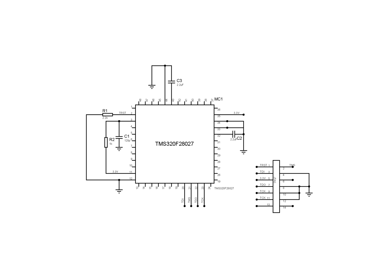
    I have attached the schematic of microcontroller connection.

    The JTAG used is Black Hawk USB2000controller.

    Please let me know if anything else is required.

  • Sachin, I took a quick glance at your schematic and I observed that you've not made any provisions for Boot mode configuration. Please check the C2000 launchpad schematics Switch S1 connections.
  • Hi Gautam,

    Thanks for the reply. I would like to know that for flash programming, should GIP034 and TDO be pulled down via 2.2k resistor. I checked the application note for bootmode SPRUF6NA but could clearly understand regarding various bootmodes .
  • Configure the Boot pins to GET mode: (From device datasheet)

  • Hi Gautam,

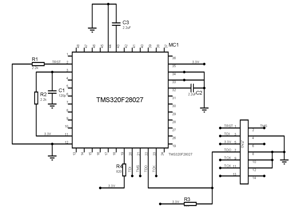
    Thanks for the reply. I have made the following changes in circuit. However the error is remaining the same.

    C28xx: Failed CPU Reset: (Error -1156 @ 0x6) Device may be operating in low-power mode. Do you want to bring it out of this mode? (Emulation package 6.0.83.0)

    In building the default Flash programme obtained from control suite, one warning was also given

    "entry-point symbol other than "_c_int00" specified:  "code_start"    Example_28027_Flash     "

    Is the issue due to hardware connection or software. and what could be done to solve it.

    Thanks.

  • Hi Sachin,

    The above schematic still doesn't have the Boot pin configuration. Can you please clarify?

    Regards,
    Gautam
  • Hi Gautam ,

    From the datasheet boot pin configuration (TDO=1, GPIO43=1, TRST=0). So I have connected TDO to 3.3V and GPIO34 to 3.3 via 820 ohm resistor. While TRST is pulled down to ground. Please tell me if there is something else to be done.

    Thanking you.
  • Sorry, my mistake. I would recommend you to go through datasheet!
    Here's another thing you've missed ie PIN 45 : If not used, should be tied to ground

    There might be many more. Please read the datasheet and do the connections accordingly! ESP. TABLE 2-2

    Regards,
    Gautam
  • Hi gautam,

    I have connected pin 45 to ground as you have mentioned . The other connections were same as before. When I build the program, I am getting

    C28xx: Trouble Halting Target CPU: (Error -1156 @ 0x6) Device may be operating in low-power mode. Do you want to bring it out of this mode? (Emulation package 6.0.83.0)
    C28xx: Trouble Halting Target CPU: (Error -1135 @ 0x0) The debug probe reported an error. Confirm debug probe configuration and connections, reset the debug probe, and retry the operation. (Emulation package 6.0.83.0)
    C28xx: Error: (Error -1135 @ 0x0) The debug probe reported an error. Confirm debug probe configuration and connections, reset the debug probe, and retry the operation. (Emulation package 6.0.83.0)

    What could be  the cause of error and how could it be rectified. Is there any particular application note which gives information on flash programming connections. Thanking you.

  • Sachin, I'm still doubtful about your connections.

    Do search the forum thoroughly for similar issues eg: e2e.ti.com/.../304496
  • Hi Gautam,

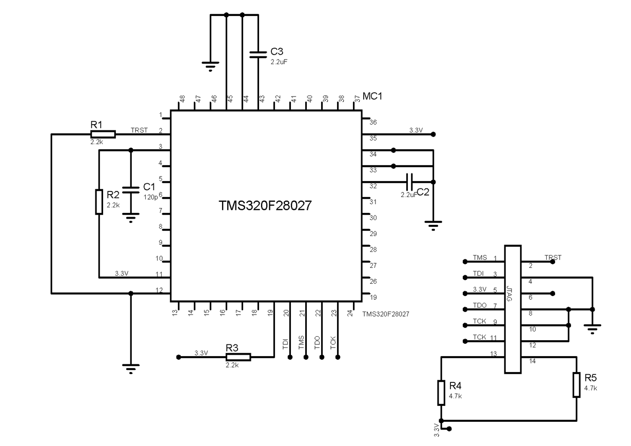
    I have made some more connection (jtag pin 13 and 14 have been pulled up through 4.7K resistors). This is the updated diagram.

    However, the problem still persists

    C28xx: Trouble Halting Target CPU: (Error -1137 @ 0x6) Device is held in reset. Take the device out of reset, and retry the operation. (Emulation package 6.0.83.0)
    C28xx: Trouble Reading Register ST1: (Error -1156 @ 0x6) Device may be operating in low-power mode. Do you want to bring it out of this mode? (Emulation package 6.0.83.0)

    In earlier connections I had given 3.3V to VDD (Pin  32, 43) . Later I had put capacitor acroos pin and ground and removed 3.3V.  I noticed that the maximum  voltage is 1.9V. I am doubtful now, if the device is damaged due to earlier connections.

    How do I know if the microcontroller is not damaged. Secondly, how to take device out of reset mode.

  • Sachin Devassy said:
    How do I know if the microcontroller is not damaged

    By checking the Temperature of the device. Is it getting very hot?

    Sachin Devassy said:
    Secondly, how to take device out of reset mode.

    That's simple XRS pin configuration. I hope its configured according to datasheet.

  • Hi Gautam,

    Thanks for the reply. The microcontroller is not getting hot. So I assume its not damaged.  XRS pin has been pulled up as shown  in schematic.  Is there any thing else to be done in connections to resolve the issue mentioned in previous post. Thanks

  • 1.8V being the core voltage, there's a possibility that it might not get hot even though its damaged. Anyways, do have a look here for alternate reason:
    e2e.ti.com/.../726918
  •  Hi Gautam,

    I have replaced the microcontroller. The connection schematic is as shown.

    Now, when i try to flash programme. I am getting the following error.

    C28xx: GEL Output:
    Device Calibration not complete, check if device is unlocked and recalibrate.C28xx: Flash Programmer: Warning: The configured device (TMS320F28027), does not match the detected device (). Flash Programming operations could be affected. Please consider modifying your target configuration file.
    C28xx: GEL Output:
    Device Calibration not complete, check if device is unlocked and recalibrate.C28xx: Flash Programmer: Device is locked or not connected. Operation cancelled.
    C28xx: File Loader: Memory write failed: Unknown error

    Is there any other settings to be done in program when flash programming a blank micocontroller. Another doubt is whether, TEST pin should be grounded or left unconnected ( as in data sheet they have metioned to leave it unconnected while in Launchpad schematic its grounded).

    Thanks

  • Sachin Devassy said:
    Is there any other settings to be done in program when flash programming a blank micocontroller. Another doubt is whether, TEST pin should be grounded or left unconnected ( as in data sheet they have metioned to leave it unconnected while in Launchpad schematic its grounded).

    Both are fine. Better left unconnected. Also verify with the F2802x controlCard schematics:

    C:\ti\controlSUITE\development_kits\~controlCARDs\CC2802xHWdevPkg

    Regards,

    Gautam

  • Sachin,
    It is hard to debug a problem like this remotely, but I can give you a few pointers.

    Do you have a Controlcard or Launchpad that you could use to verify that CCS is able to estalish a connection to the target device and talk to it? This would validate your CCS installation and settings. If this is working, you could try to program a small COFF file in flash. With this, you have established that the tools/software part is good. You could now turn your focus to your hardware. Use the ControlCard/Launchpad schematics as a reference. If the power-supply, boot-mode and JTAG pins are correctly connected, CCS must be able to connect to your board. Probe the -XRS pinto make sure the WD is not timing out and repeatedly resetting the device. This shouldn’t happen if you have connected the boot-mode pins appropriately.