This thread has been locked.

If you have a related question, please click the "Ask a related question" button in the top right corner. The newly created question will be automatically linked to this question.

CCS/TMS320F28377S: SCI ISN'T PROPERLY WORKING

Part Number: TMS320F28377S

Tool/software: Code Composer Studio

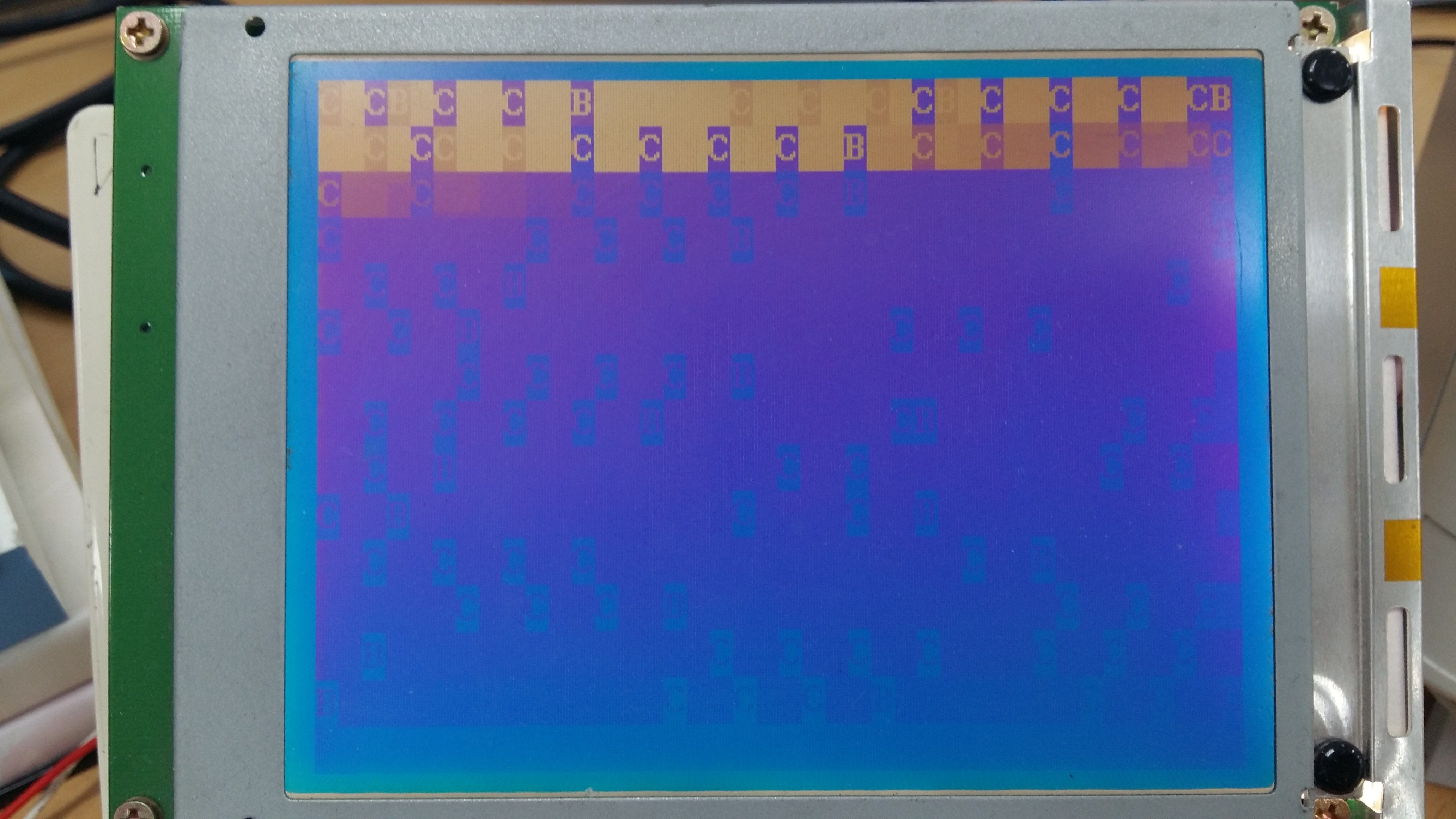
LCD monitor should have pictured as below view through SCI TXDA  connection...

  • eeddii,

    Can please give a description on your problem?

    Please make sure to include any screenshots, if any.

    Thanks,

    Vince Rodriguez
  • Hi
    Yes , of course . SCI-A TXDA is making wrong signal instead of to display ADC.RESULT values as I want . I want to see in LCD monitor voltage sensor values through SCI-A TXDA connection . To do this I used ASCII format . Here the code main is :


    /*
    * main.c
    *
    * Created on: 2017. 5. 11.
    *
    */

    #include "F28x_Project.h"
    #include "math.h"
    #include "main.h"
    #include <string.h>

    extern interrupt void adca1_isr(void);
    extern void InitEPwm(void);
    extern void ConfigureADC(void);
    extern void Gpio_setup(void);

    extern void InitSci(void);
    extern void InitSpi(void);
    extern void OUT_Display(void);

    extern void Function_Init(void);
    extern void Value_Init(void);
    extern void Control_filter_Init(void);

    extern void FULL_SYSTEM_DISABLE(void);
    void Sys_Init(void);

    extern void Write_mode(char mode);
    extern void GLcd_Clear(char n);
    extern void GLcd_Glayer(char n);
    extern void GLcd_Cursor_OnOff(char mode);
    extern void GLcd_Cursor_mode(char mode);
    extern void BL_OnOff(char mode);
    extern void GLcd_FontStyle(void);

    extern void ValuetoAsii(long value, int digit, int fract, char *str, char zero_fill);
    extern void GLcd_Out(char *data, char num);
    extern void GLcd_Text_Loc(const char x, const char y);


    ///////////////////////////////////////////////////////////////////////////////////////////////////////////////////////////////

    void MemCopy(Uint16 *SourceAddr, Uint16* SourceEndAddr, Uint16* DestAddr)
    {
    while(SourceAddr < SourceEndAddr)
    {
    *DestAddr++ = *SourceAddr++;
    }
    return;
    }

    void main(void)
    {
    //
    // Step 1. Initialize System Control:
    // PLL, WatchDog, enable Peripheral Clocks
    // This example function is found in the F2837xS_SysCtrl.c file.
    //
    InitSysCtrl();
    InitGpio();
    DINT;

    EALLOW;
    CpuSysRegs.PCLKCR0.bit.TBCLKSYNC = 0;
    EDIS;

    InitPieCtrl();

    IER = 0x0000;
    IFR = 0x0000;

    EALLOW;
    CpuSysRegs.PCLKCR0.bit.TBCLKSYNC = 1;
    EDIS;

    InitPieVectTable();

    DELAY_US(1000);
    ConfigureADC();
    Sys_Init();

    Function_Init();
    Value_Init();
    Control_filter_Init();

    EALLOW;
    PieVectTable.ADCA1_INT = &adca1_isr;
    EDIS;

    PieCtrlRegs.PIEIER1.bit.INTx1 = 1;
    PieCtrlRegs.PIEIER9.bit.INTx1 = 1; // PIE Group 9, INT1, SCI RX Interrupt
    PieCtrlRegs.PIEIER9.bit.INTx2 = 1; // PIE Group 9, INT2, SCI TX Interrupt

    IER |= M_INT1; //Enable group 1 interrupts // EPWM and ADC int...
    IER |= M_INT3;

    PieCtrlRegs.PIECTRL.bit.ENPIE = 1;
    PieCtrlRegs.PIEACK.all = 0xFFFF;

    EINT; // Enable Global interrupt INTM
    ERTM; // Enable Global realtime interrupt DBGM

    while (1)
    // for (;;)
    {
    OUT_Display(); // LCD displaying part
    }
    }

    void Sys_Init(void)
    {
    Gpio_setup();
    InitEPwm();
    InitSci();
    InitSpi();

    Write_mode(0);
    GLcd_Clear(0);
    GLcd_Glayer(2);

    GLcd_Cursor_OnOff(0);
    GLcd_Cursor_mode(0);
    BL_OnOff(1);
    }

    void InitSci(void)
    {
    #define USE_SCIA 1
    #define USE_SCIB 0
    #define USE_SCIC 0
    #define USE_SCID 0

    #if USE_SCIA
    Scia();
    Sciagpio();

    #endif

    #if USE_SCIB
    Scib();
    #endif

    #if USE_SCIC
    Scic();
    #endif

    #if USE_SCID
    Scid();
    #endif
    }

    #if USE_SCIA
    void Scia(void)
    { SCIA_EN = 2;
    // Note: Clocks were turned on to the SCIA peripheral in the InitSysCtrl() function SCICHAR
    SciaRegs.SCICCR.all = 0x0007; // 1 stop bit, No loopback, No parity,8 char bits, async mode, idle-line protocol
    SciaRegs.SCICTL1.all = 0x0003;
    SciaRegs.SCICTL2.all = 0x0003;

    // SciaRegs.SCICTL2.bit.RXBKINTENA = 1;
    // SCIA at 9600 baud
    // @LSPCLK = 50 MHz (200 MHz SYSCLK) HBAUD = 0x02 and LBAUD = 0x8B.
    SciaRegs.SCIHBAUD.all = 0x02;
    SciaRegs.SCILBAUD.all = 0x145;///325 decimal

    SciaRegs.SCICTL1.all = 0x0023; // Relinquish SCI from Reset
    }
    #endif

    void Sciagpio(void)
    {
    GpioCtrlRegs.GPCPUD.bit.GPIO84 = 0; // Enable pullup on GPIO84
    GpioCtrlRegs.GPCGMUX2.bit.GPIO84 = 1; // GPIO84 = peripheral out
    GpioCtrlRegs.GPCMUX2.bit.GPIO84 = 1; // GPIO84 = SCI TXDA
    GpioCtrlRegs.GPCDIR.bit.GPIO84 = 1; // GPIO84 = output

    GpioCtrlRegs.GPCPUD.bit.GPIO85 = 0; // Enable pullup on GPIO85
    GpioCtrlRegs.GPCGMUX2.bit.GPIO85 = 1; // GPIO85 = SCI RXDA
    GpioCtrlRegs.GPCMUX2.bit.GPIO85 = 1; // GPIO84 = SCI RXDA
    GpioCtrlRegs.GPCDIR.bit.GPIO85 = 0; // GPIO85 = input
    }
    } //// END OF MAIN()

    //////// THIS IS LCD DISPLAYING PARTS ///////////////////////
    #include "F28x_Project.h"
    #include "main.h"
    #include "math.h"
    #include "stdio.h"
    #include "string.h"

    #pragma CODE_SECTION(OUT_Display, ".TI.ramfunc");

    void ValuetoAsii(long value, int digit, int fract, char *str, char zero_fill);
    void GLcd_Out(char *data, char num);
    void GLcd_Text_Loc(char x, char y);
    void OUT_Display(void);


    extern int16 AD_RESULT_A[16], AD_RESULT_B[16];
    char cValue[10],LCD_LINE_COUNT=0;
    Uint16 LCD_MODE = 0, V_dcc_ref = 1542;
    int32_t dataOut32;


    ///////////////////////////////////////////////////////////////////////////////////////////////////////////////////////////////////////////////////


    void OUT_Display(void)
    {
    switch(LCD_MODE)
    {
    case 0:
    LCD_LINE_COUNT=0;
    GLcd_Text_Loc(0, LCD_LINE_COUNT);
    GLcd_Out("AD0 :", 6);
    ValuetoAsii((long)AD_RESULT_A[0], 4, 0, cValue, 0); // AD_RESULT_A[0] = ADC voltage sensor
    GLcd_Out(cValue, 4);

    GLcd_Out(" AD1 :", 6);
    ValuetoAsii((long)AD_RESULT_A[1], 4, 0, cValue, 0);
    GLcd_Out(cValue, 4);

    GLcd_Out(" AD2 :", 6);
    ValuetoAsii((long)AD_RESULT_A[2], 4, 0, cValue, 0);
    GLcd_Out(cValue, 4);

    GLcd_Out(" AD3 :", 6);
    ValuetoAsii((long)AD_RESULT_A[3], 4, 0, cValue, 0);
    GLcd_Out(cValue, 4);

    // Line2 Display
    LCD_LINE_COUNT++;
    GLcd_Text_Loc(0, LCD_LINE_COUNT);
    GLcd_Out("AD4 :", 6);
    ValuetoAsii((long)AD_RESULT_A[4], 4, 0, cValue, 0);
    GLcd_Out(cValue, 4);

    GLcd_Out(" AD5 :", 6);
    ValuetoAsii((long)AD_RESULT_A[5], 4, 0, cValue, 0);
    GLcd_Out(cValue, 4);

    GLcd_Out(" AD6 :", 6);
    ValuetoAsii((long)AD_RESULT_A[6], 4, 0, cValue, 0);
    GLcd_Out(cValue, 4);

    GLcd_Out(" AD7 :", 6);
    ValuetoAsii((long)AD_RESULT_A[7], 4, 0, cValue, 0);
    GLcd_Out(cValue, 4);

    // Line3 Display
    LCD_LINE_COUNT++;
    GLcd_Text_Loc(0, LCD_LINE_COUNT);
    GLcd_Out("AD8 :", 5);
    ValuetoAsii((long)AD_RESULT_A[8], 4, 0, cValue, 0);
    GLcd_Out(cValue, 4);

    GLcd_Out(" AD9 :", 6);
    ValuetoAsii((long)AD_RESULT_A[9], 4, 0, cValue, 0);
    GLcd_Out(cValue, 4);

    GLcd_Out(" AD10:", 6);
    ValuetoAsii((long)AD_RESULT_A[10], 4, 0, cValue, 0);
    GLcd_Out(cValue, 4);

    GLcd_Out(" AD11:", 6);
    ValuetoAsii((long)AD_RESULT_A[11], 4, 0, cValue, 0);
    GLcd_Out(cValue, 4);
    break;
    }}

    void GLcd_Text_Loc(const char x, const char y)
    { // GLcd_Text_Loc(0, LCD_LINE_COUNT);
    char data[5];
    data[0] = 0x1B;
    data[1] = 0x4C;
    data[2] = 0x4F;
    data[3] = x; // x 좌표(0 ~ 39)
    data[4] = y; // y 좌표(0 ~ 14)
    GLcd_Out(data, 5);
    }

    void GLcd_Out(char *data, char num)
    {
    char ctemp, i;
    for(i=0; i<num; i++){
    ctemp = *data++;
    SciaRegs.SCITXBUF.all = ctemp;
    while(SciaRegs.SCICTL2.bit.TXRDY!= 1) { } // wait for XRDY =1 for empty stateTXDT
    }
    }
    // End of file
    //
  • LCD monitor picture below is currently wrong dispplaying ADC values in decimal format .
  • Vincent ,

    Can you response quickly please ?
  • eeddii,

    From looking at the LCD monitor, i do not believe that decimal to ASCII conversion is the only problem.

    Here are some debug steps I would perform to see if we can isolate the problem.

    1. Check what kind of packet format you need to be sending the LCD monitor. You might need to send more than just the ASCII character.
    2. Set a breakpoint inside your ASCII conversion function, and check to make sure you are converting to ASCII correctly.

    Let me know how that goes.

    Thanks,

    Vince Rodriguez
  • Hi Vince !

    Only ASCII character value to be sent LCD monitor.
    2. I've made breakpoint , a some delay inside ASCII conversion function , but any success .
  • eeddii,

    when you set your breakpoint was the value of the the ASCII conversion function the correct value?