This thread has been locked.

If you have a related question, please click the "Ask a related question" button in the top right corner. The newly created question will be automatically linked to this question.

more urgent!TMS320F28335: a urgent 28335 ADC problem

Part Number: TMS320F28335
Other Parts Discussed in Thread: CONTROLSUITE

My Customers use 28335 for their motor control products. Recently, in their production test ,they found some DSP’s ADC results are wrong. For example, the normal value is 10, but when the problem occur, the value is 1000.


Their product has been in production for many years without any similar problem. And  they have not change the HW and SW. So they suspect that the problem may be caused by the batch of DSP, they did some tests, the most convincing one is: remove the “problem”  DSP to the normal board, the problem can be reproduced.  

I think we can’t judge this problem caused by the batch of DSP only by the test, so can you provide some other test methods to locate the problem?


I have do some tests with the engineers these days, and the testing process and results are as follows:


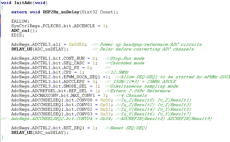
  • Modify some of the ADC initialization code ,The code they used before is as below:


      AdcRegs.ADCTRL3.all = 0xE0;

      DELAY_US(ADC_usDELAY);


We modified the code as below,


       AdcRegs.ADCTRL3.bit.ADCBGRFDN = 0x3;   

       DELAY_US(1000)                         

       AdcRegs.ADCTRL3.bit.ADCPWDN = 1;       

       DELAY_US(1000);                        


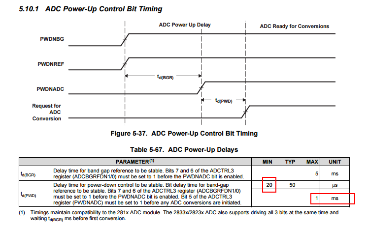
  We founded that the longer of the delay time, the less times of the ADC problem.


My question is, what are the differences between the two different initialization methods?  I found that most examples in the ControlSUITE use the first way.


What are the requirements before the ADC initialization, for example, how long time we should wait before the initialization….                                                                                                                                 


  • In the compiler Opt Level option, select different levels of optimization, we found that the times of the problem will change.


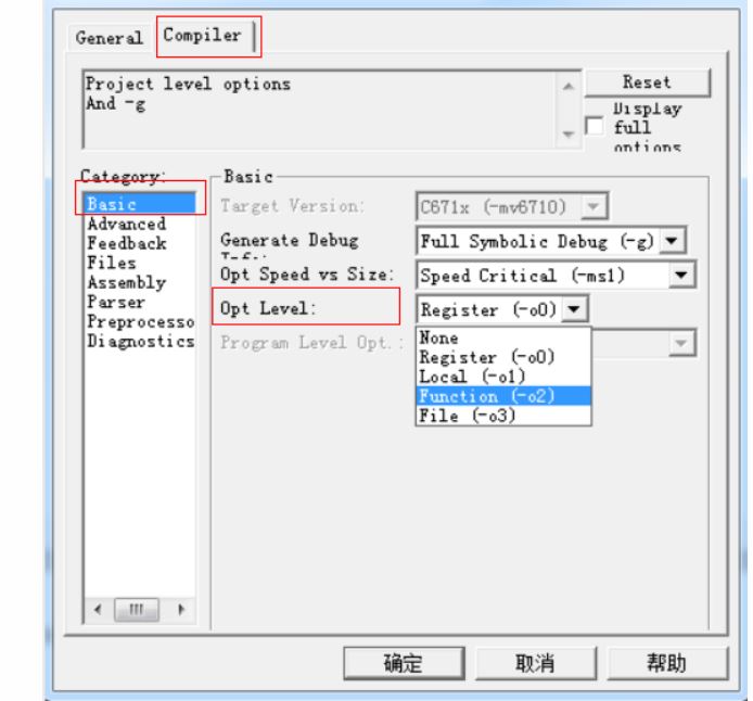
What is the difference between different Opt Level and how to choose the optimal level for the optimization?

  • Does any can give a hand for this probem.
  • Hi Shuai,

    The power up/down sequence is described in the ADC UG in section 1.6 "Power-up Sequence"

    You would normally power-up and power-down the ADC by setting / clearing all 3 bits at once as per your first method. In the second method, you are powering up the references and bandgaps first, then the ADC next. This shouldn't affect the total power-up time for you.

    If you had completely powered everything up, then shut just the ADC down (not the BG and references) then you can power the ADC up in 20us.

    As far as the delays/optimization, for correct operation, you must wait at least 5ms after full power up before using the ADC. It is possible that optimization level is reducing or eliminating this time. You can measure the execution time between any two points when debugging (in CPU cycles) using the profiler:

    processors.wiki.ti.com/.../Profile_clock_in_CCS

    It may be a good idea to verify the actual run time delay between ADC power-up and first ADC trigger.
  • Hi Devin,

    Very appreciate  for helping me all the time.

    Today I have do some test with customer engineer, and found a strange phenomenon ,

    We add some code(nothing to do with the ADC Init) in the main function, for example : the yellow back ground is the code we add,

    We found that ,when adding the code(not limit to this “if” code, any code is ok), the ADC worked normally, when remove the code, the ADC result are wrong!

    It is unbelievable! Unable to explain this ! The only possibility I can think of is  that: when add the code , the location of the InitAdc() function stored in the flash may changed.

    Another thing is that, the customer’s V1.02 SW worked normally, the V1.03 SW worked abnormal. These two SW used the same  initialization process and ADC Init code, and the difference between the two version SW is the V1.03 is bigger than the V1.02 .

    Can you give me some ideas about this? Thank you!                            

    void main(void)

    {

    Int a = 1;

      InitSysCtrl();                                        

      MemCopy(&RamfuncsLoadStart, &RamfuncsLoadEnd, &RamfuncsRunStart);

      InitFlash();

      DINT;

      InitPieCtrl();

      IER = 0x0000;

      IFR = 0x0000;

      InitPieVectTable();

      EALLOW;

      PieVectTable.ADCINT1        = &Current_Isr;            

      EDIS;

      PieCtrlRegs.PIECTRL.bit.ENPIE = 1;              // Enable the PIE block

      PieCtrlRegs.PIEIER1.bit.INTx1 = 1;              // Enable PIE Group 1,

      InitGpio();      

      InitAdc();                            

    If(a==0)

    {

    }

    ……..

    }

  •  Hi Devin,

    Thanks for your help , we do a lot of test today, maybe we have found the cause of this problem : after the InitADC(), we read the value of the ADC Register ,found that the value of  “ADCTRL1 ADCTRL2  ADCTRL3” are all zero! The InitADC() failed to configure the ADC register!Below is the code they used:


    What are the possible reasons that cause the register configure failed?


    And another test is as you have mentioned: “If you had completely powered everything up, then shut just the ADC down (not the BG and references) then you can power the ADC up in 20us.


    We use above code to power the ADC, found that this way can reduce the frequency of the problem. Have you ever encountered similar problems? Do you have any experience or basis for this proposal?

  • Hi Shuai,

    For the power-up time, the suggestion was directly taken from the module documentation:

    But based on the datasheet, you should still probably wait at least 1ms in this case and not 20us, as 20us is the best case power-up time.

    As far as why your registers aren't getting correctly initialized depending on some adding/removing unrelated code, I'll ask someone else to comment. 

  • Hi Shuai,

    You might also want to take a look at this e2e post where inserting unrelated code (NOPs in this case) caused some issues with the ADC. The root cause appears to be incorrect flash settings.

    e2e.ti.com/.../2143701

    Because of this, it may be a good idea to try executing from RAM to see if you have better results. If running from RAM directly is better, you can target changing the flash settings and/or mem copy functions to fix your issue.
  • Hi Devin,
    During the weekend, my customer modify the SW, executing the ADCInit() from RAM to see if have better results, they still doing the test. And now, they have not encounted the problem,it seems that this way have a effective result.

    I have get the map file of their project, for the “problem” project and the “no problem” project, found that the ADCInit() located from the same flash address. May be because for the two projects, the 28335 Init code is the same.

    Another phenomenon is that: For the same “problem” project, not all the DSP have the problem, some DSP worked normally all the time . Do you know what caused the difference?(for example, different batch dsp have different sensitivity)

    I have read the e2e.ti.com/.../2143701, maybe I could not get the point of this . Does it mean that the difference of the flash access wait time can cause similar problem?
  • When executing code from flash, the location of the code may have an effect on the performance. There is a prefetching mechanism on the flash. If code is moved around and or branches are added to the code then the performance may vary because the prefectching may behave differently. This may cause some timing issues between the different builds.

    Please use the Clock feature in CCS to profile this. Run->Clock->Enable.

    sal

  • Sal,
    Thanks, maybe I could not get the point of this . Does it mean that the difference of the flash access wait time can cause similar problem? Do you mean that if the code execute from the flash, there will be a risk ? The "different bulids" means different compiler or different config of the compiler?