This thread has been locked.

If you have a related question, please click the "Ask a related question" button in the top right corner. The newly created question will be automatically linked to this question.

TIDM-BIDIR-400-12: Boost operation problems for the Bi-directional buck boost phase shift converter under light load

Part Number: TIDM-BIDIR-400-12
Other Parts Discussed in Thread: TMS320F28035

Hallo Everyone,

I am working on DC/DC phase shift full bridge converter as also given by TI using C2000 TMS320F28035 controller. The problem i have found so far with the topology description in Boost mode. Push Pull current fed boost topology is not described in detail in TI document as its buck operation in document "TIDUAi7.pdf ".

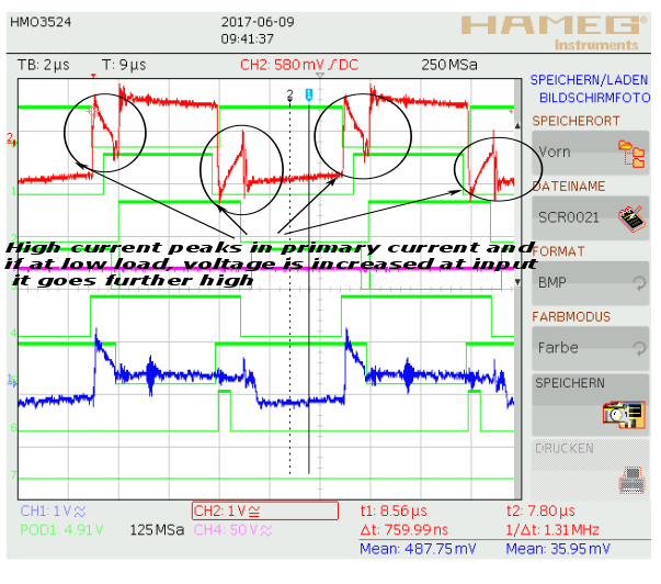
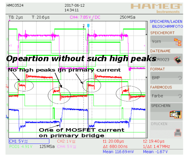
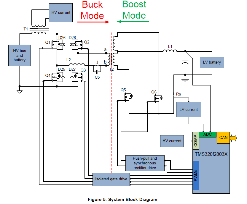
Even i have found a TI document containing calculations for Buck operation in "slua560c". But similar not found for Boost mode. I am getting high current peaks at low load and it damages anytime the Mosfets.The problem is shown in fig1 and in fig2 normal operation without such high peaks is shown. Circuit diagram in Fig3.

It would be really really nice if someone sends the Boost mode description in different intervals and its waveforms or explain why this problem is coming under light load condition when i turn-on the full bridge with phase shiftedPWM and secondary side push pull MOSFET's with different duty cycle and 180° phase apart as explained in TI manual.

Also let me know if the below circuit is correct or it needs some changes? i have also two diodes on primary side which are given by TI also..

  • Hi,

    The circuit diagram you mention is a high level block diagram of the system. Please refer to the schematic files with the detailed circuit diagram.

    Are you using a board you built that is based on the TI design files that come with TIDUAI7 (http://www.ti.com/tool/TIDM-BIDIR-400-12? Are you using the 400V - 12V bi-directional DC-DC software from TI (which comes with this TI design)? Can you please describe your test set-up? 

    Thank you.

    Hrishi

  • HI,

    I have also a PCB as perTI design files but with TI design files the problem comes because of signal distortions . The Controller stop functioning after distortions and USB connection from PC disconnects everytime when i go to 12 V input in Boost mode. I am also trying and resolving issues with it.
    Secondly as mentioned in my previous description that Boost operation is not described as i have found about the Buck operation documentation for the same topology. Specially calculations in Buck operation .Is it possible to send me operational description of boost operation for this topology and current waveforms of primary side trafo or bridge current for different input voltages and load conditions which are not described in its description manual.

    I shall be thankful if you can provide so i can compare the actual results and sort out this problem.