


Dear Champion,
My customer using F28069 for the PFC control, in order to achieve the ZCD (Zero crossing detection), they using the GPIO as the ZCD signal and connected to ECAP pin.
However, in the power supply with the switching noisy we affect the capture result.
Does team had better idea to fix the problem? below are the code and the waveform.
thanks for your comment.
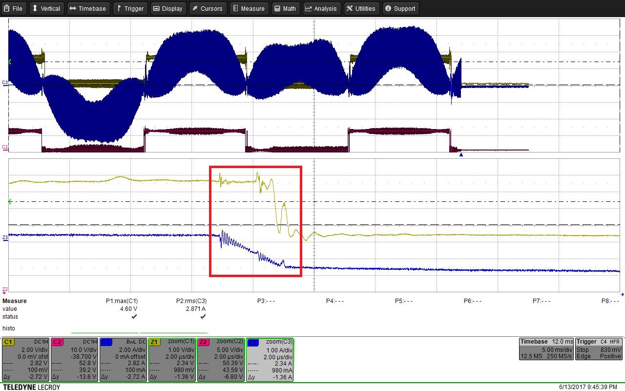
Ch1: ZCD Signal(connect to Capture pin); Ch2: PWM; Ch3: Inductor current.
void InitECap1Gpio(void)
{
EALLOW;
GpioCtrlRegs.GPAPUD.bit.GPIO24 = 1; // Enable pull-up on GPIO24 (CAP1)

// Inputs are synchronized to SYSCLKOUT by default.
// Comment out other unwanted lines.

// GpioCtrlRegs.GPAQSEL1.bit.GPIO5 = 0; // Synch to SYSCLKOUT GPIO5 (CAP1)
// GpioCtrlRegs.GPAQSEL1.bit.GPIO11 = 0; // Synch to SYSCLKOUT GPIO11 (CAP1)
// GpioCtrlRegs.GPAQSEL2.bit.GPIO19 = 0; // Synch to SYSCLKOUT GPIO19 (CAP1)

//Qualification using 6 samples.Valid for pins configured as GPIO or a peripheral function.The
//time between samples is specified in the GPACTRL register
GpioCtrlRegs.GPAQSEL2.bit.GPIO24 = 0x10; //GPIO24 (CAP1)

//Specifies the sampling period for pins GPIO24 to GPIO31.
//sampling Period = 2*255 × TSYSCLKOUT
GpioCtrlRegs.GPACTRL.bit.QUALPRD3 = 0xFF;

/* Configure eCAP-1 pins using GPIO regs*/
// This specifies which of the possible GPIO pins will be eCAP1 functional pins.
// Comment out other unwanted lines.

// GpioCtrlRegs.GPAMUX1.bit.GPIO5 = 3; // Configure GPIO5 as CAP1
// GpioCtrlRegs.GPAMUX1.bit.GPIO11 = 3; // Configure GPIO11 as CAP1
// GpioCtrlRegs.GPAMUX2.bit.GPIO19 = 3; // Configure GPIO19 as CAP1
GpioCtrlRegs.GPAMUX2.bit.GPIO24 = 1; // Configure GPIO24 as CAP1

EDIS;
}


void Capture_setting()
{
ECap1Regs.ECEINT.all = 0x0000; // Disable all capture interrupts
ECap1Regs.ECCLR.all = 0xFFFF; // Clear all CAP interrupt flags
ECap1Regs.ECCTL1.bit.CAPLDEN = 0; // Disable CAP1-CAP4 register loads
ECap1Regs.ECCTL2.bit.TSCTRSTOP = 0; // Make sure the counter is stopped

// Configure peripheral registers
ECap1Regs.ECCTL2.bit.CONT_ONESHT = 0; // continuous
ECap1Regs.ECCTL2.bit.STOP_WRAP = 1; // wrap after capture-EVT2(CEVT2) in continuous
ECap1Regs.ECCTL1.bit.CAP1POL = 0; // Rising edge occur CEVT1,正緣觸發為正半週zcd
ECap1Regs.ECCTL1.bit.CAP2POL = 1; // Falling edgeoccur CEVT2,負緣觸發為負半週zcd
//ECap1Regs.ECCTL1.bit.CAP3POL = 1; // Falling edge
//ECap1Regs.ECCTL1.bit.CAP4POL = 0; // Rising edge
ECap1Regs.ECCTL1.bit.CTRRST1 = 1; // Difference operation(when CEVT1 occur, after capture count then reset CNTR)
//ECap1Regs.ECCTL1.bit.CTRRST2 = 1; // Difference operation
//ECap1Regs.ECCTL1.bit.CTRRST3 = 1; // Difference operation
//ECap1Regs.ECCTL1.bit.CTRRST4 = 1; // Difference operation
//ECap1Regs.ECCTL2.bit.SYNCI_EN = 1; // Enable sync in
//ECap1Regs.ECCTL2.bit.SYNCO_SEL = 0; // Pass through
ECap1Regs.ECCTL1.bit.CAPLDEN = 1; // Enable capture units

ECap1Regs.ECCTL1.bit.FREE_SOFT = 0;//TSCTR counter stops immediately on emulation suspend

ECap1Regs.ECCTL2.bit.TSCTRSTOP = 1; // Start Counter
ECap1Regs.ECCTL2.bit.REARM = 1; // arm one-shot
ECap1Regs.ECCTL1.bit.CAPLDEN = 1; // Enable CAP1-CAP4 register loads
ECap1Regs.ECEINT.bit.CEVT1 = 1; // 1 events = interrupt
ECap1Regs.ECEINT.bit.CEVT2 = 1; // 1 events = interrupt
ECap1Regs.ECEINT.bit.CTROVF = 1; // OVERFLOW = interrupt

}
