Part Number: TMS320F28027F
Hello,
I am working on a project for an e-bike motor controller, I am using the controller TMS320F28027F, which is built on a custom board. before addressing the problem I'd like to mentioned all used elements.I am using Lab4 from InstaSPIN FOC. The torque ADC value is indicated from 0 to 5v.
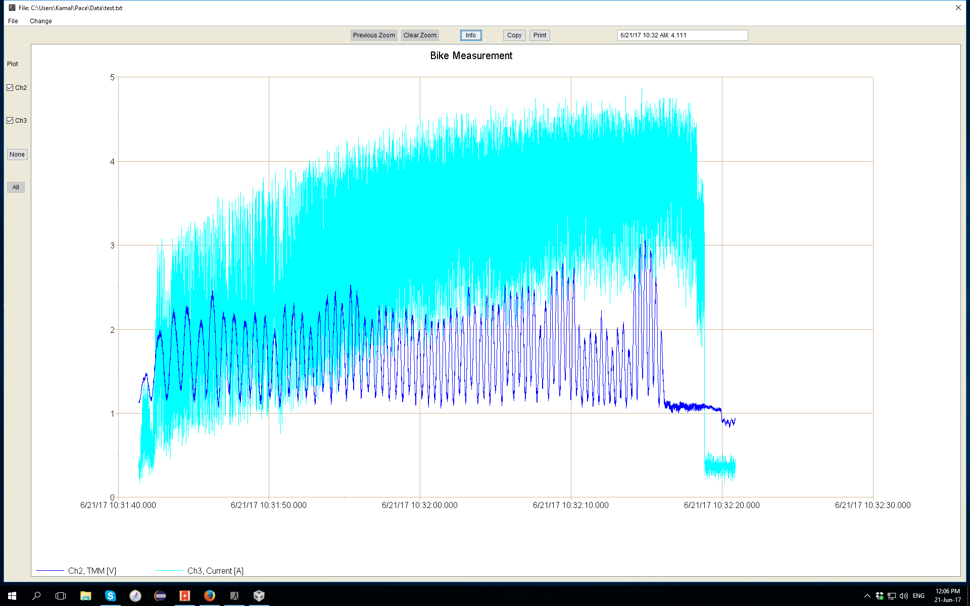
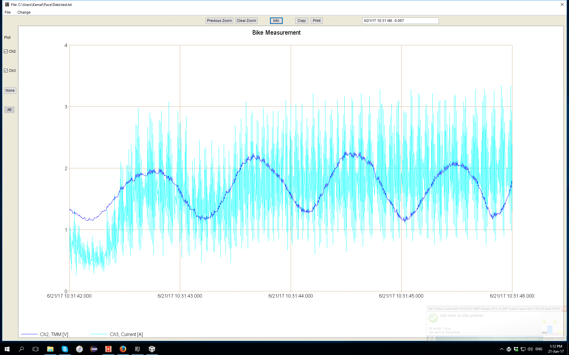
The controller works fine on different PMSM motors, including one direct drive motor. the problem, there is one direct drive PMSM, which I am facing problems with. The below attached pictures (2&3) shows how it looks on the direct drive motor, which is not good.
the motor parameters (I don't have the motor specs, I have followed the guide to reach the below values)
#define USER_SYSTEM_FREQ_MHz (60.0)
#define USER_PWM_FREQ_kHz (30.0)
#elif (USER_MOTOR == MI_motor)
#define USER_MOTOR_TYPE MOTOR_Type_Pm
#define USER_MOTOR_NUM_POLE_PAIRS (7)
#define USER_MOTOR_Rr (NULL)
#define USER_MOTOR_Rs
#define USER_MOTOR_Ls_d
#define USER_MOTOR_Ls_q
#define USER_MOTOR_RATED_FLUX
#define USER_MOTOR_MAGNETIZING_CURRENT (NULL)
#define USER_MOTOR_RES_EST_CURRENT (5.0)
#define USER_MOTOR_IND_EST_CURRENT (-5.0)
#define USER_MOTOR_MAX_CURRENT (40)
#define USER_MOTOR_FLUX_EST_FREQ_Hz (10)
It should look like attachment 1 but it comes out as attachment 2 and 3.
any tips or suggestions are highly appreciated
Blue is the input signal 0 to 5v & light blue is the output signal 0 to 40A.
attachment 1

attachment 2