This thread has been locked.

If you have a related question, please click the "Ask a related question" button in the top right corner. The newly created question will be automatically linked to this question.

TMS320F28377D: ePWM clock and TBCLK settings, is there a limit

Part Number: TMS320F28377D


Hi there,

I am using TMS320F28377D and I am looking for some clarifications, for correcting my understanding of the EPWM clock. It would be great if you could help.

In my software I have set:

ClkCfgRegs.PERCLKDIVSEL.bit.EPWMCLKDIV = 0;

EPwm6Regs.TBCTL.bit.CLKDIV = 0;

EPwm6Regs.TBCTL.bit.HSPCLKDIV = 0;

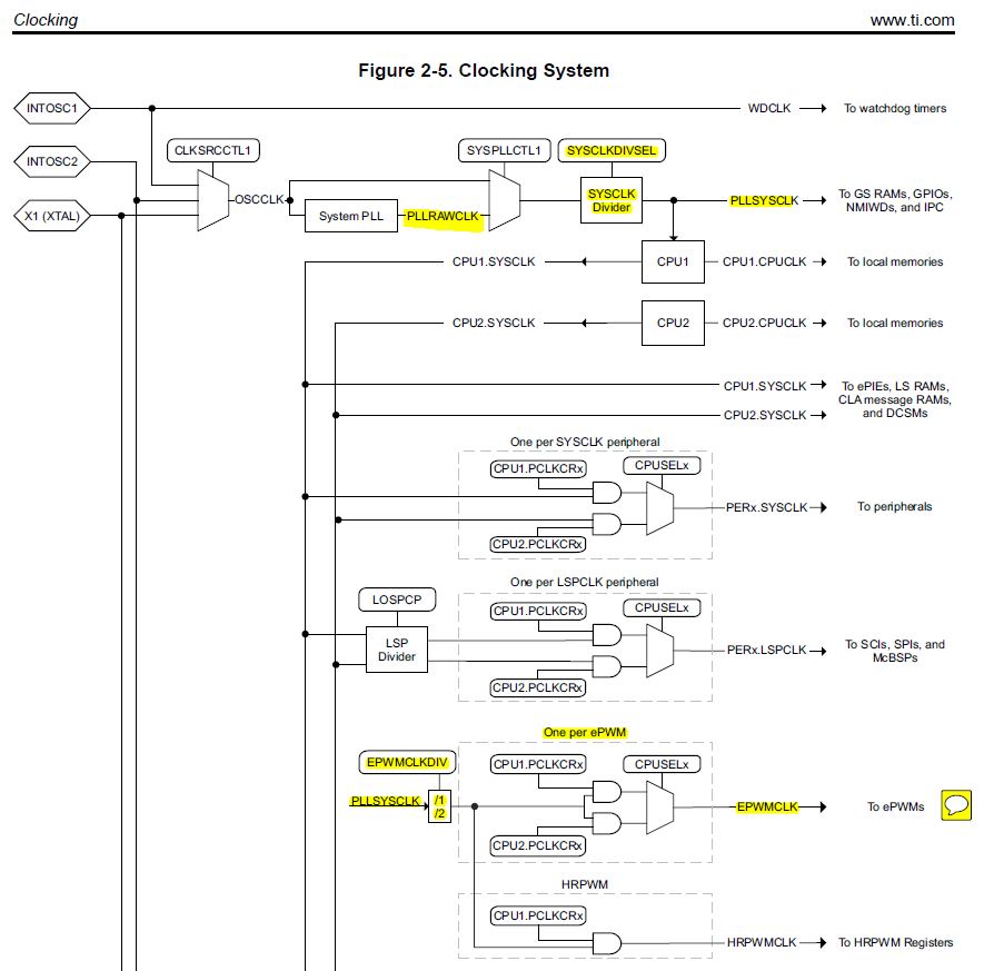
so according to SPRUM8C, Fig. 13-5 pag. 1478


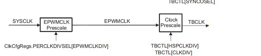
my ePWM TBCLK should be the system clock, i.e. TBCLK = 1/200MHZ = 5 x 10^-9 =5ns.

I am using EPWM6 in UP-DOWN mode, and I have setup

EPwm6Regs.TBPRD = 500;

so the PWM period is TPWM = 2 * TBPRD * TBCLK = 5 x 10^-6 = 5us (SPRUHM8C, pag. 1480), i.e. I am switching the converter at 200kHz, and I can see this from my actual setup. I assume that this means that my calculations above are correct.

The questions are:

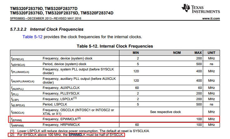
(1)  Is there any limit on the TBLCK, i.e. am I using a TBCLK too low? (is there a 100MHz limit?)

(2) Also, I have noticed that:


ClkCfgRegs.SYSCLKDIVSEL.bit.PLLSYSCLKDIV = 1

 is this influencing my calculation above? Is the system clock still 200MHz? even with the above set  PLLSYSCLKDIV = 1?

Thank you for your kind help,

Leo


  • Hi Leo,

    The ePWM clock is indeed limited to 100MHz.  Setting it higher will cause unpredictable operation.

    There are a variety of valid ways to achieve the same SYSCLK setting using different clock sources, input clock frequencies, and PLL settings.  As long as these settings are valid, there shouldn't be any difference to downstream modules like the ePWM (except for obvious stuff like an input clock with worse frequency accuracy will result in reduced frequency accuracy for the downstream modules).  Some ways the clock source settings could be invalid would be too low or high of an input frequency to the PLL or too high or low of a PLL raw clock (the clock before the divider you quoted).

  • Hello Devin,

    Thank you very much for your answer, it is of great help.

    So, it is clear that I need to change my settings above in order to have an EPWMCLK of 100MHz, I can do that by leaving:

    ClkCfgRegs.PERCLKDIVSEL.bit.EPWMCLKDIV = 1; // note set to 1 in order to have EPWMCLK = 100MHz
    
    EPwm6Regs.TBCTL.bit.CLKDIV = 0;
    
    EPwm6Regs.TBCTL.bit.HSPCLKDIV = 0;

    What I am still a bit confused about is the function of the PLLSYSCLKDIV. Perhaps I don't understand how the following setting

    ClkCfgRegs.SYSCLKDIVSEL.bit.PLLSYSCLKDIV = 1

    relates to the PWM CLOCK.... Is setting this PLL system clk divider = 1 making the PWM clock = 100MHz in some way? 

    Thank you again,

    Leo

  • Hi Leo,

    Yeah, you should set ClkCfgRegs.PERCLKDIVSEL.bit.EPWMCLKDIV = 1. This will result in ePWM clock = SYSCLK / 2. If SYSCLK is 200MHz this will give you 100MHz ePWM clock. If you ran the CPU at 100MHz for some reason, you could instead set this bit to 0.

    As far as the PLL settings, see 2.7 "Clocking" in the TRM. Roughly, you have an input clock that is usually 10MHz-20MHz. This gets multiplied by the PLL to form the PLL raw clock, which is maybe 400MHz. Then this gets divided by the PLL divider to form the SYSCLK @ 200MHz. The divider you are referring to affects the PLL raw clock to SYSCLK ratio, which will affect the eventual ePWM clock (but also most other clocks on the device).
  • Hello Devin,

    Thank you very much, I got it. I attach the below picture from the TRM SPRUHM8e (pag. 106) for reference. 

    Basically, in my setup the PLLRAWCLK is 400MHz, and by setting

    ClkCfgRegs.SYSCLKDIVSEL.bit.PLLSYSCLKDIV = 1

    then the PLLSYSCLK is 200MHz.

    Now I must set 

    ClkCfgRegs.PERCLKDIVSEL.bit.EPWMCLKDIV = 1; 

    in order to have a EPWMCLK = PLLSYSCLK / 2 = 100MHz.

    All clear now, thank you.

    Leo