This thread has been locked.

If you have a related question, please click the "Ask a related question" button in the top right corner. The newly created question will be automatically linked to this question.

TMS320F28027: Device held in reset issue

Part Number: TMS320F28027
Other Parts Discussed in Thread: CONTROLSUITE

Hello, 

as I do more research about possible issue, i only get more confused. I got written a code that works on C2000 LaunchPadXL http://www.ti.com/tool/launchxl-f28027

As i try to debug i get this message:
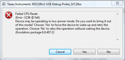
If i press YES or NO, no matter i get 2nd message:

C28xx: Failed Software Reset: A reset is already in progress: (Error -1137 @ 0x0) Device is held in reset. Take the device out of reset, and retry

the operation. (Emulation package 6.0.407.3)"

And i can't figure out how to take device out of reset and how this reset appears?

There is some confusing things for me:

As  I use TMS320F28027PTS in my board (instead TMS320F28027PTT in developement board) i found that some suppliers declare that power supply voltage for this MCU is 1.71 V ~ 1.995 V, some other says that it is 3.3V. So who is right and maybe there is an issue why programming doesn't works for me? 

  • I also get this message (when turining device on, trst, TDO and GPIO34 set ON). It also shows that device does not match configured device, but there is TMS320F28027 soldered in...

    ---------------------------------------------------------------------------------------------------------------------------------------------------------------------------------
    C28xx: Failed CPU Reset: (Error -1137 @ 0x6) Device is held in reset. Take the device out of reset, and retry the operation. (Emulation package 6.0.407.3)
    C28xx: Trouble Reading Register PC: (Error -1137 @ 0x0) Device is held in reset. Take the device out of reset, and retry the operation. (Emulation package 6.0.407.3)
    C28xx: Trouble Reading Register ST1: (Error -1137 @ 0x6) Device is held in reset. Take the device out of reset, and retry the operation. (Emulation package 6.0.407.3)
    C28xx: GEL: Error while executing OnReset(1): Target failed to read register ST1
    at (ST1&~(0x0100)) [f28027.gel:283]
    at C28x_Mode() [f28027.gel:33]
    at OnReset(1)
    C28xx: Flash Programmer: Warning: The configured device (TMS320F28027), does not match the detected device (). Flash Programming operations could be affected. Please consider modifying your target configuration file.
    C28xx: Error enabling this function: ACU_SEL Register write failed
    C28xx: Failed CPU Reset: (Error -1137 @ 0x0) Device is held in reset. Take the device out of reset, and retry the operation. (Emulation package 6.0.407.3)
    C28xx: Trouble Reading Register PC: (Error -1137 @ 0x0) Device is held in reset. Take the device out of reset, and retry the operation. (Emulation package 6.0.407.3)
    C28xx: Trouble Reading Register ST1: (Error -1137 @ 0x6) Device is held in reset. Take the device out of reset, and retry the operation. (Emulation package 6.0.407.3)
    C28xx: GEL: Error while executing OnReset(1): Target failed to read register ST1
    at (ST1&~(0x0100)) [f28027.gel:283]
    at C28x_Mode() [f28027.gel:33]
    at OnReset(1)
    C28xx: Trouble Writing Memory Block at 0x0 on Page 0 of Length 0x2: (Error -1137 @ 0x6) Device is held in reset. Take the device out of reset, and retry the operation. (Emulation package 6.0.407.3)
    C28xx: File Loader: Verification failed: Target failed to write 0x00000@Program
    C28xx: GEL: File: C:\ti\controlSUITE\device_support\f2802x\v230\f2802x_examples_structs\scia_loopback\Debug\Example_2802xScia_FFDLB.out: Load failed.
  • As i figured out so far, i missed one point. In development board VDD1 and VDD2 are connected to GND via capacitors. So as i found, there is internal LDO for MCU core. Did this core powers up from 3.3V power supply inputs like VDDIO? And how this LDO are enabled if MCU has no program uploaded? Tomorrow i'll try to disconnect VDD1 and 2 from 3.3V, i hope i didn't damaged MCU....
  • Julius,

    I believe that most of this information can be found in the device manual:

    Let us know if something is unclear.

    -Tommy

  • Julius,

    The LAUNCHXL-F20827 uses the internal LDO to take the 3.3V VDDIO supply to 1.8V for the VDD supply. The VDD pins, while in this mode are still required to have decoupling capacitors to GND. At least 1.2uF caps are required to be between each VDD pin and GND (See Table 4-1 Signal Descriptions in the datasheet - SPRS523). The internal LDO is enabled by tying the VREGENZ pin to GND. 

    There is a risk that your device may be damaged by putting 3.3V on the VDD pins.

    Please read through the Datasheet (SPRS523) and System Control and Interrupts Users Guide - Section 7.1 On-Chip Voltage Regulator (VREG) (SPRUFN3) 

    Regards,
    Mark