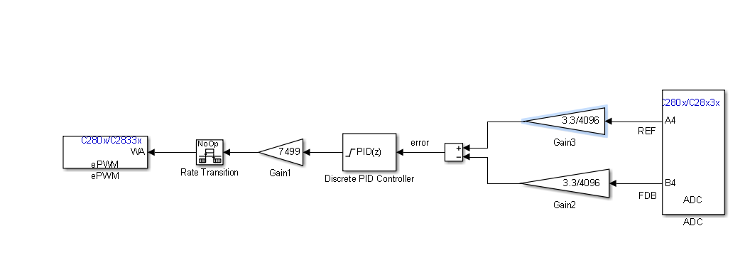
Tool/software: Code Composer Studio
Hello,
I tried a more methodical approach to designing the PID for a boost converter. I used frequency response estimation of plant controller and I also used the system Identification toolbox on the simulation I implemented in order to linearize the plant transfer function about the PID and get the PID coefficients. Unfortunately, neither methods worked well. The constants gotten from the first method didn't even work with the boost converter simulation let alone actual design, while the constants for the second method gave a super slow response (like 1 sec settling time) in discrete time mode. Since I have previously designed the ordinary closed boost converter using analog method (op-amps), I knew the integrator constants that worked well for me in both simulation and on breadboard design (Ki = 10). So I decided to discretize the integrator (with a sampling time of 0.01s) and use it with f28335 but it is not working well.
I need HELP!
Kindly find attached.
plus 7499 is TBPRD (Up-count). Parallel PID.


