
- Ask a related questionWhat is a related question?A related question is a question created from another question. When the related question is created, it will be automatically linked to the original question.

Hello guys,
I've been working with a DCL in F28069M using a PI controller to regulate current on some coils. I was using J-tag window to adjust my variables and everything was going well till I tried to add the SCI feature to my project in order to make a GUI for my device using C#.
I used SCIA interrupt features and I could send and receive a customized formatted string from my PC to my launchpad F28069M and everything went fine, I could check all the values in the debug window and I made sure my SCI connection/communication works perfectly fine!
But when I switched to real project, with activated SCIA interrupt, I can send and receive data but non of my GPIO's are working now !!! The coils are controlled through some GPIOs and I turn them on by selecting a specific GPIO pin which is activates the specific coil.
The GPIO pins I'm using are : 17-19-44-50-51-55. When I start the code the GPIO states remains on, which they must go low!(I think they remain pulled-up on input state)
So what do you think is my problem?
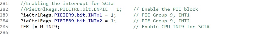
when I activate this part of my code everything goes wrong:
Regards
Milad


