This thread has been locked.

If you have a related question, please click the "Ask a related question" button in the top right corner. The newly created question will be automatically linked to this question.

CCS/TMS320F28052F: Motor Current consumption peak

Part Number: TMS320F28052F


Tool/software: Code Composer Studio

We have been working on a sensorless motor control with INStaspin FOC (on a TMS320F28052F). 

The motor has 2 poles pair, and is working at 40v, 10A max, 3.5 krpm max speed. PWM is at 30 kHz, system run at 60 mHz.

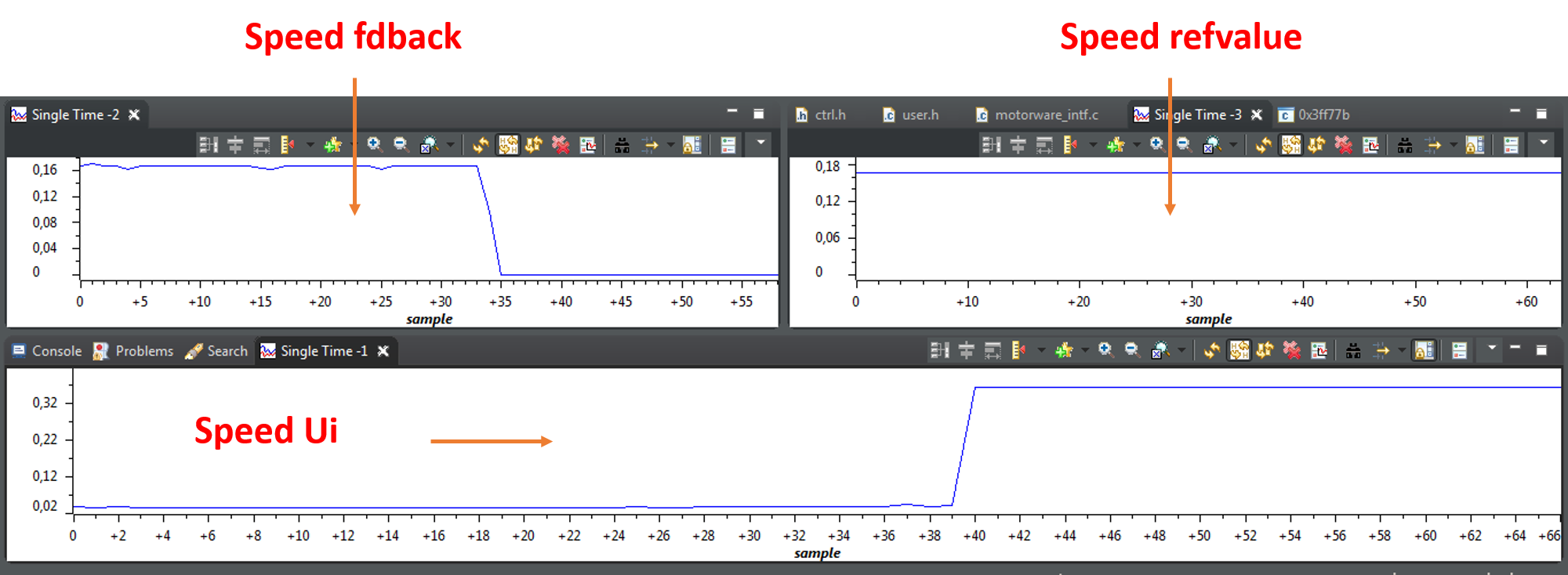
i'm making the motor spin at 2.5krpm and i then stop it brutally on the shaft
what i want to achieve, is to monitor the current consumption so that its level always stay below 2 Amps
To do so, i monitor the max out of speed PID in ctrl.h (PID_setMinMax(obj->pidHandle_spd,outMin,outMax);) and i use the formula Is_A = sqrt ( Iq_A x Iq_A + Id_A x Id_A )

 _iq Is_A, Id_A_temp, Iq_A_temp;
 Is_A = _IQ(2.0);
 Id_A_temp = _IQmpy(CTRL_getId_in_pu(handle), _IQ(USER_IQ_FULL_SCALE_CURRENT_A));
 Iq_A_temp = _IQsqrt(_IQmpy(Is_A, Is_A) - _IQmpy(Id_A_temp, Id_A_temp));
 Iq_A_temp = _IQdiv(Iq_A_temp, _IQ(USER_IQ_FULL_SCALE_CURRENT_A));

 if(Iq_A_temp < outMax)
 {
 		outMax = Iq_A_temp;
 		outMin = -outMax;
 }
 PID_setMinMax(obj->pidHandle_spd,outMin,outMax);

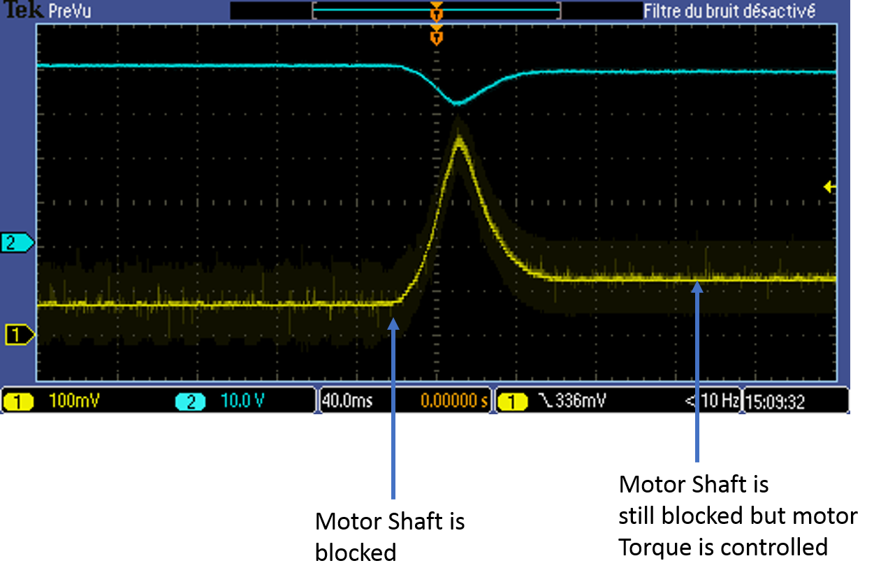
That seems to work when the motor is stopped. What i observe, is that there is a peak of current during the stop and i don't understand why ? Can anyone provide me hints ?


Yellow curve is the Current with 100mV/A resolution
Blue curve is the Voltage in V

  • Is the current waveform from DC bus of power supply? Did you have the motor phase current waveform? What's the MAXIMUM CURRENT in your projects?

    The torque current will be up to maximum current if you block the rotor of motor, so will have a current ramp up as you showed. And the power supply output power is not enough in this case, so the dcbus voltage will drop to keep constant power output.
  • Yes the waveform are both from the DC bus of power supply. I don't have a motor phase current waveform yet.

    I've set the maximum current to 

    #define USER_MOTOR_MAX_CURRENT          (8.0)

    I agree that the torque current would be up to maximum current if i blocked the shaft but the purpose of my modification in ctrl.h is to limit it when doing so.

    As i said on the figure, when the shaft is still blocked, i can control the current (it won't go to 8.0 Amps, you can see it stall at 2.3 Amps). My problem happen not when the motor is stopped but when it is being stopped.

  • Need to monitor the the PI regulator of Iq and speed, to check the reference, feedback and Ui. What's the Ui when appear the motor shaft is blocked and appeared peak current?
  • I tried to sample the values with Code Composer debug.

    The Ui for the speed regulator appears as : 

    The Ui for the IQ regulator appears as : 

  • I'm still stuck on this and monitoring Vdq doesn't help :-(
    Any hints ?
  • Did you have the scope waveform for motor phase current when you start to block the motor shaft?
    And did you disable the speed close loop immediately when you blocked the motor? It seems the Ui of speed and Iq_ref increase quickly when you blocked the motor, the motor input power will increase higher than DC power supply output capacity.
  • scope waveform for motor phase current :

    Yellow curve is the Current on Power supply
    Blue curve is the Voltage in V
    Purple curve is the current on phase B

    I don't disable the speed close loop when i block the motor (i don't want too), why should i ? As soon as i release the motor, i want to do speed control to get back to the speed before blocking.

     "the motor input power will increase higher than DC power supply output capacity." => yes, that's what's happening, but limiting Ui in both PID (Iq and speed) should be enough to limit current consumption, doesn't it ?