This thread has been locked.

If you have a related question, please click the "Ask a related question" button in the top right corner. The newly created question will be automatically linked to this question.

TMS320F28069: F28069 PLL EMI

Part Number: TMS320F28069
Other Parts Discussed in Thread: TMDSDOCK28069

Hi TI experts,

My customer uses F28069 , and do a EMI verification of vehicle regulations.

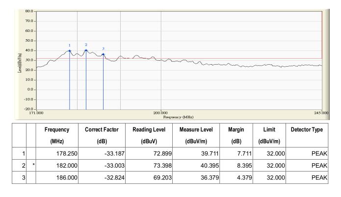
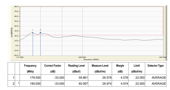
Failures of 90MHz & 180 MHz radio noise  were found with MCU run at 90MHz system clock. (as below picture)

1. How to reduce these radio EMI of MCU PLL?

2. What are the difference MCU behaviors of "PLLCR=18,PLLSTS[DIVSEL] = 2,(OSCCLK*18/2) "and "PLLCR=9,PLLSTS[DIVSEL] = 3,(OSCCLK*9/1)"?

thanks,

best regards,

Simen

  • Simen,

    Do the peaks move if the PLL is programmed to another frequency?

    The PLL-generated frequency is internal to the device so I think that the most likely path for radiation would be through the VDD power supply. Are decoupling capacitors placed close to the F2806x power pins?

    -Tommy
  • Hi Tommy,

    1.
    180Mhz noise appears after program begins to run.

    2.
    Customer's PCB has put 2.2 uF capacitors each power pin (VDD & VDDIO) and close to pin out.


    best regards,
    Simen
  • Simen,

    Can you see if peaks move when the SYSCLK frequency is changed? For example, if PLL is set to 60MHz, do the peaks move to 60MHz / 120MHz?

    Is the system using an external clock source or the zero-pin internal oscillator?

    Is VDD powered by VREG or an external source?

    -Tommy
  • Hi Tommy,

    1. we change sysclk to 70 MHz and the peak rise up at 70 MHz, and 140MHz appears, 180Mhz become very low.

    (show it as Figure 1 )

       Another issue is 30MHz and 60MHz noise appear with unknown reason when power on.

      This situation also happens at TMDSDOCK28069 and TMDX28069USB.

      (show it as Figure 2 , scan EMI form TMDSDOCK28069)

    2. System uses external 10 MHz clock.

    3. VDD powered by internal VREG.

    (Figure 1)

    (Figure 2)

    best  regards,

    Simen

  • Simen,

    A colleague who is more familiar with EMC testing asked if you are using a quasi-peaks method of detection. The F28069 LaunchPad had smaller SYSCLK spikes with quasi-peak detection.

    A fundamental in the 120-125MHz range would probably be the XDS100 CPLD.

    I am not sure about the 30MHz fundamental. Is there any preloaded code that might be toggling pins at power up?

    -Tommy
  • Tommy,

    Quasi-peak method detection is OK.

    The 90Mhz and 180 Mhz of peak method and average method detection are over limit.

    Let us get focus back how to solve 90Mhz and 180 Mhz EMI.

    90Mhz is system clock, 180MHz is PLL , system CLKOUT pin is disable.

    Any others ideas ?

    thanks,

    below pictures are customer's board DEKRA report.

    best regards,

    Simen

  • Simen,

                    I don’t claim to be an expert, but I will help as I can. Can you explain your device to me? Keep in mind and try to answer the questions below.

    What kind of device are you trying to qualify? What standards are you trying to meet?

    • Is it a PCB?
    • Does it have a case?
    • Is the case metallic?
    • Is the case properly grounded?
    • Are there any small openings in the case that may allow EMI radiation to escape?
    • Has the case accidently become an antenna rather than a shield?
    • What mitigation techniques have you tried so far?
    • What EMI design rules, if any, were followed when laying out the device?
    • Did you perform any design simulations for EMI?

    Regards,
    Cody


  • Dear Cody

    I am MCU FAE located in Taiwan.

    Is it a PCB?
    Yes, it is the PCB designed by customer.

    Does it have a case?
    The PCB module is in the case.

    Is the case metallic?
    One side of the case is made by plastic and another side is aluminum.

    Is the case properly grounded?
    The PCB ground is connected to the aluminum of the case.
    Do you mean the case should connect with a ground?
    I will send the picture to you in a separated email.

    Are there any small openings in the case that may allow EMI radiation to escape?
    There is no hole in the plastic side but there is a small hole in the aluminum side.

    Has the case accidently become an antenna rather than a shield?
    We try to test it by a probe and the signal get stronger when the probe close to F28069.
    Without the case, the EMI become stronger.

    What mitigation techniques have you tried so far?
    What EMI design rules, if any, were followed when laying out the device?
    Did you perform any design simulations for EMI?

    They just follow the design of our EVM without special mitigation technologies to prevent EMI.
    May I send the schematics and gerber to you for review?
    Customer try to test F28069 ControlCard and also get 90MHz and 180MHz EMI issue.
    Do you have any test report on our EVM?

    Thanks for your support.

  • All,

                At this point it sounds like it is not related to the casing of the device, let’s explore other options.

    Debug:

    • Try switching the device to internal oscillator and see if the issue persists.
    • Place some EMI shielding tape on the device, what is the effect?

    Concerns about layout(see ti.com/lit/spraas1c ):

    • Crystal layout, must be close to device
    • Decoupling capacitor layout and value
    • Keep power loops small


    Jefferey said:

    Do you mean the case should connect with a ground?
    I will send the picture to you in a separated email.


                <CW> No need, it sounds like your case is working correctly.

    Regards,
    Cody