This thread has been locked.

If you have a related question, please click the "Ask a related question" button in the top right corner. The newly created question will be automatically linked to this question.

TMS320F28379D: can i read the adc result "just in time" in CPU?

Part Number: TMS320F28379D

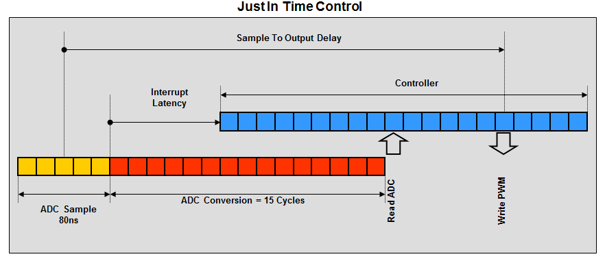
A important feature for CLA is that it can read the adc result "just in time" to minimize the current loop latency, how about the CPU? Are there any examples?

Thanks.

  • Hi Howard,

    There are a few methods to consider for 'just in time' control loop updates.

    1. On most of our families of devices (F2802x and newer), the ADC has Early Interrupt functionality.  When the ADC is configured in this mode, it means that the ADC will trigger an interrupt after it has completed sampling (but before it has started to convert).  This means that much of the conversion processes will occur as the CPU is changing contexts to the interrupt.  This can be one method of doing 'just in time' updates.  The picture below describes the idea.

    2. In many cases the ePWM module is generating the ADC SOC trigger and it is possible for the ePWM to generate the control loop's interrupt instead of the ADC.  If done, it provides a method to minimize control loop latency if utilized correctly - the user needs to make sure that any ADC conversions are complete before the ADC result is used. 
      1. In many cases the ePWM compare event that is used to generate the ADC SOC would also generate the ISR.
      2. On newer devices, like the F2837*, the ePWM module contains extra counter compare registers.  CMPC & CMPD are largely there in order to enable the customer to more flexibly generate their ePWM interrupts relative to the ADC SOC trigger so that more Just In Time optimization is possible (among other things).


    The method described in 2a is done in a number of the system-based evaluation kit examples, but I don't believe it is really documented that we are doing it.

    Hopefully this helps!

    Thank you,
    Brett

  • Hi Howard,

    Just to add a couple more bits of info to add to Brett's answer:

    You can get the exact ISR context switch latency timings here (14 cycles for an internal interrupt):

    processors.wiki.ti.com/.../Interrupt_FAQ_for_C2000

    You can get the exact ADC timings out the F2837xD datasheet from Table 5-51. "ADC Timings in 12-Bit Mode (SYSCLK Cycles)" and Table 5-52. "ADC Timings in 16-Bit Mode".  There are also accompanying diagrams.  From this, you will notice that in the normal use case of SYSCLK = 200MHz and ADCCLK = 50MHz the timings are as follows: 

    12-bit mode: early INT occurs at 1 cycle, results latch at 44 cycles.  Therefore if you use early interrupt mode you will need to wait or do setup operations for 44-1-14 = 29 cycles. 

    16-bit mode: early INT occurs at 1 cycle, results latch at 120 cycles.  Therefore if you use early interrupt mode you will need to wait or do setup operations for 120-1-14 = 105 cycles. 

     For both modes, if you use late interrupt mode, you arrive in the ISR 14 cycles after the results have latched.

    Now, on the F28004x device family we have added an additional feature that lets you delay the ISR generation in early interrupt mode by an arbitrary number of cycles.  You do this by putting the device into early interrupt mode and then writing a value to ADCINTCYCLE.DELAY.  In the 12-bit case above, you could write 29 to this register and then enter the ISR exactly on time.  If you had 6 cycles of setup before you need to read the result, you could instead write 29-6 = 23 and still arrive at the read operation exactly on time.