This thread has been locked.

If you have a related question, please click the "Ask a related question" button in the top right corner. The newly created question will be automatically linked to this question.

TMS320F28075: GPIO Input Qualification and detection

Part Number: TMS320F28075

Hello,

I have a GPIO configured as input to the tripzone. I also have input qualification 6 samples at SYSCLKOUT of 10ns. The configuration is as follows:

EALLOW;
GpioCtrlRegs.GPAINV.bit.GPIO31 = 1; 	         /* TZ active low - Input inversion control for this pin */
GpioCtrlRegs.GPACTRL.bit.QUALPRD3 = 0;      /* Qual period = SYSCLKOUT = 10ns */
GpioCtrlRegs.GPAQSEL2.bit.GPIO31 = 2;  	/* Qual Samples = 6; Total samples=10 and if input is high for 6 samples (6*10ns=60ns), then it is REALLY high. */
GpioCtrlRegs.GPAPUD.bit.GPIO31 = 1;       	/* Enable pull-up on GPIO (TZx) - 1: Disables the Pull-Up. */
InputXbarRegs.INPUT1SELECT = 31; 		/* INPUT1 is link with TZ1 - PFC_TRIP */
EDIS;

My understanding is that if a signal is to be detected as actual input, it has to be high for 6 continuous samples. My question is that if it detect first 3 samples as high and next three as low, will the count start from 0 or from 4 for next sampling window?

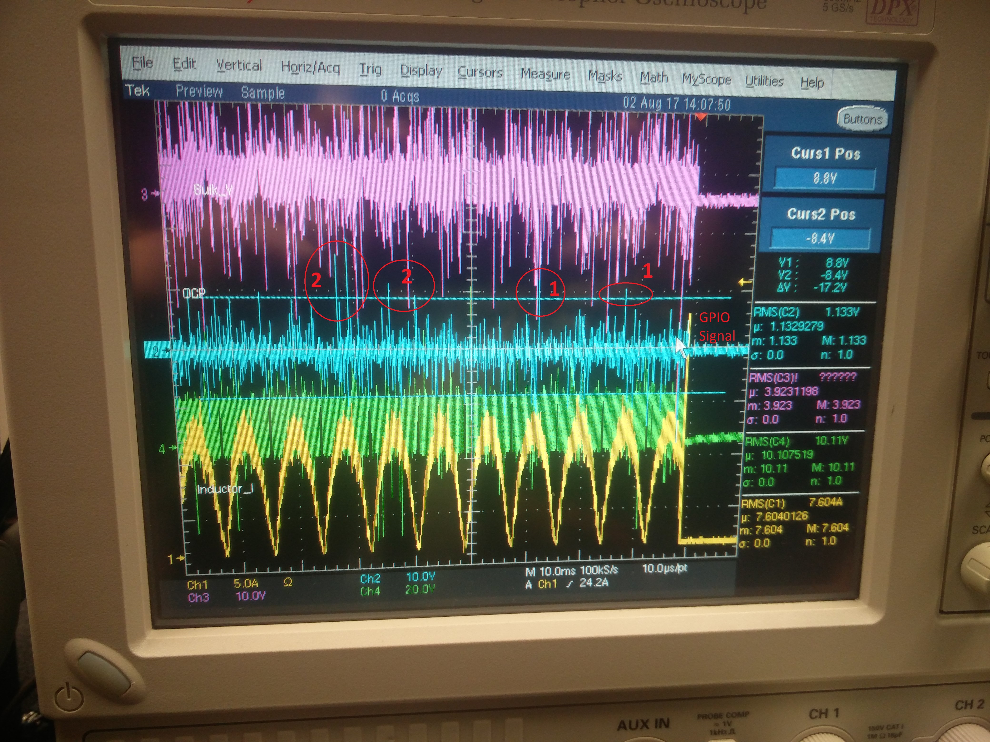
In my system, one the input is high, I shut down the system. In the following oscilloscope picture, I see 6 high samples before shutting down but the timing is totally different (in terms of ms). It gives me an impression that it does not reset the counter value or something which is being used to check continuous 6 samples for high.

What am I missing?

  • Hello,
    I am writing to let you know that a C2000 team member has been assigned to this post and should be answering shortly.

    Regards
    Baskaran
  • Hi Sagar,

    The qualification logic should reset back to 0 each time the signal clears. Looking at the waveform, I imagine you're using qualification because of the noise on the input signal. What is the source of that signal that is so noisy?

    Can you explain what you are showing with the circles (1) and (2) on the waveform? It looks like your scope is set to 10 V/division so the crossing you are showing is almost 10 V if I'm reading it correctly.

    Regards,
    Kris
  • I apologize. I thought I replied to this one but did not.

    Yes, I tried to use qualification because of the noise on the input signal. The source is some over current protection signal coming out of op-amp.

    I was trying to show the crossings in the circle. But I am wrong. As you rightly pointed out, the scale is too high for micro-controller pin. May be the GPIO is getting set for the noise itself but not the actual signal.

    We will work on to get the clean signal and then we will see how it works out for us.

    Thanks you,
    Sagar
  • Sagar,

    Getting those signals cleaned up is going to be critical to achieving a reliable system. I think your development will go much smoother afterwards.

    Regards,
    Kris