This thread has been locked.

If you have a related question, please click the "Ask a related question" button in the top right corner. The newly created question will be automatically linked to this question.

CCS/TMS320F28379D: Input sensing in MCU and transferring the same data to the CAN Receiver and Transmitter terminals

Part Number: TMS320F28379D


Tool/software: Code Composer Studio

Hi all,

          I am working on CAN based message transfer between two microcontrollers in Code Composer Studio software environment. The block diagram structure of the communication interface is as below:

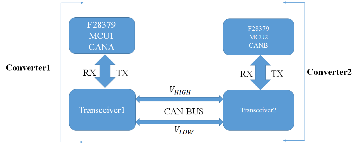
With reference to the above diagram, the application which needs to be developed through programming consists of several steps:

In case of a Fault occuring in Converter2 (DC-AC 3-phase Inverter),

(a)  Fault in Conv2 has to be sensed by MCU2.

(b) MCU2 has to communicate the fault status to MCU1.

(c) Accordingly MCU1 will generate the gating signals to Conv1 in order to reduce the DC link voltage to zero.

(d) Finally the Input voltage of Conv2 will be zero, thereby the same will stopped working and supplying 3-phase output power to the load.

      I will be highly obliged if someone can suggest the programming to be done for the situation mentioned above.

      Thanking You.

Regards

Sumanta


  • Hi all,

    I got stuck with the problem as mentioned above for a couple of days and is unable to find out a feasible solution. Can anyone suggest how to modify the source code in CAN_Loopback program so that the 2 MCU cards will have feature of communicating message over CAN bus for a particular disturbance.

    Thanks in advance.

    Regards
    Sumanta
  • Hi Sumantha,

    Please see the modified code that you can try out.  Take note of the comments i put that start with "// INFO:".  Code will not compile as it is as you need to define the proper functions that you are running, but the sample below should give you an idea on what to modify and where to place the function calls. You can use similar code for each MCU and you can actually connect as many nodes as you need to the CAN bus.  It would be good to assign a unique ID for each MCU so you know which node transmitted the fault condition. Hope the sample code helps.

    Regards,

    Joseph

    //###########################################################################
    //
    // FILE: can_loopback.c
    //
    // TITLE: Example to demonstrate basic CAN setup and use.
    //
    //! \addtogroup cpu01_example_list
    //! <h1>CAN External Loopback (can_loopback)</h1>
    //!
    //! This example shows the basic setup of CAN in order to transmit and receive
    //! messages on the CAN bus. The CAN peripheral is configured to transmit
    //! messages with a specific CAN ID. A message is then transmitted once per
    //! second, using a simple delay loop for timing. The message that is sent is
    //! a 4 byte message that contains an incrementing pattern. A CAN interrupt
    //! handler is used to confirm message transmission and count the number of
    //! messages that have been sent.
    //!
    //! This example sets up the CAN controller in External Loopback test mode.
    //! Data transmitted is visible on the CAN0TX pin and can be received with
    //! an appropriate mailbox configuration.
    //!
    //
    //###########################################################################
    // $TI Release: F2837xD Support Library v200 $
    // $Release Date: Tue Jun 21 13:00:02 CDT 2016 $
    // $Copyright: Copyright (C) 2013-2016 Texas Instruments Incorporated -
    // http://www.ti.com/ ALL RIGHTS RESERVED $
    //###########################################################################

    //
    // Included Files
    //
    #include "F28x_Project.h"
    #include <stdint.h>
    #include <stdbool.h>
    #include "inc/hw_types.h"
    #include "inc/hw_memmap.h"
    #include "inc/hw_can.h"
    #include "driverlib/can.h"

    //
    // Globals
    //
    volatile unsigned long g_ulMsgCount = 0; // A counter that keeps track of the
    // number of times the transmit was
    // successful.
    volatile unsigned long g_bErrFlag = 0; // A flag to indicate that some
    // transmission error occurred.

    //
    // Main
    //
    int
    main(void)
    {
    tCANMsgObject sTXCANMessage;
    tCANMsgObject sRXCANMessage;
    unsigned char ucTXMsgData[4], ucRXMsgData[4];

    //
    // Step 1. Initialize System Control:
    // PLL, WatchDog, enable Peripheral Clocks
    // This example function is found in the F2837xD_SysCtrl.c file.
    //
    InitSysCtrl();

    //
    // Step 2. Initialize GPIO:
    // This example function is found in the F2837xD_Gpio.c file and
    // illustrates how to set the GPIO to its default state.
    //
    InitGpio();
    GPIO_SetupPinMux(30, GPIO_MUX_CPU1, 1); //GPIO30 - CANRXA
    GPIO_SetupPinMux(31, GPIO_MUX_CPU1, 1); //GPIO31 - CANTXA
    GPIO_SetupPinOptions(30, GPIO_INPUT, GPIO_ASYNC);
    GPIO_SetupPinOptions(31, GPIO_OUTPUT, GPIO_PUSHPULL);

    //
    // Initialize the CAN controller
    //
    CANInit(CANA_BASE);

    //
    // Setup CAN to be clocked off the M3/Master subsystem clock
    //
    CANClkSourceSelect(CANA_BASE, 0);

    //
    // Set up the bit rate for the CAN bus. This function sets up the CAN
    // bus timing for a nominal configuration. You can achieve more control
    // over the CAN bus timing by using the function CANBitTimingSet() instead
    // of this one, if needed.
    // In this example, the CAN bus is set to 500 kHz. In the function below,
    // the call to SysCtlClockGet() is used to determine the clock rate that
    // is used for clocking the CAN peripheral. This can be replaced with a
    // fixed value if you know the value of the system clock, saving the extra
    // function call. For some parts, the CAN peripheral is clocked by a fixed
    // 8 MHz regardless of the system clock in which case the call to
    // SysCtlClockGet() should be replaced with 8000000. Consult the data
    // sheet for more information about CAN peripheral clocking.
    //
    CANBitRateSet(CANA_BASE, 200000000, 500000);

    //
    // Step 3. Clear all interrupts and initialize PIE vector table:
    // Disable CPU interrupts
    //
    DINT;

    //
    // Initialize the PIE control registers to their default state.
    // The default state is all PIE interrupts disabled and flags
    // are cleared.
    // This function is found in the F2837xD_PieCtrl.c file.
    //
    InitPieCtrl();

    //
    // Disable CPU interrupts and clear all CPU interrupt flags:
    //
    IER = 0x0000;
    IFR = 0x0000;

    //
    // Initialize the PIE vector table with pointers to the shell Interrupt
    // Service Routines (ISR).
    // This will populate the entire table, even if the interrupt
    // is not used in this example. This is useful for debug purposes.
    // The shell ISR routines are found in F2837xD_DefaultIsr.c.
    // This function is found in F2837xD_PieVect.c.
    //
    InitPieVectTable();

    //
    // Enable test mode and select external loopback
    //
    //HWREG(CANA_BASE + CAN_O_CTL) |= CAN_CTL_TEST;
    HWREG(CANA_BASE + CAN_O_TEST) = CAN_TEST_EXL;

    //
    // Enable the CAN for operation.
    //
    CANEnable(CANA_BASE);

    //
    // Initialize the message object that will be used for receiving CAN
    // messages.
    //
    *(unsigned long *)ucRXMsgData = 0;
    sRXCANMessage.ui32MsgID = 1; // CAN message ID - use 1
    sRXCANMessage.ui32MsgIDMask = 0; // no mask needed for TX
    sRXCANMessage.ui32Flags = MSG_OBJ_NO_FLAGS;
    sRXCANMessage.ui32MsgLen = sizeof(ucRXMsgData); // size of message is 4
    sRXCANMessage.pucMsgData = ucRXMsgData; // ptr to message content

    //
    // Setup the message object being used to receive messages
    //
    CANMessageSet(CANA_BASE, 2, &sRXCANMessage, MSG_OBJ_TYPE_RX);


    while(1) // INFO: Place this portion in part of the program where the MCUs are able to run functions
    { // that can result in faults
    faultOccured = OtherMCUFunction1(); // INFO: This will be the function that will return if fault occured in the MCU
    faultCode = OtherMCUFunction2(); // INFO: This will be the function that will determine the fault code
    RestOfMCUFunctions();
    :
    :
    :
    TransmitAndMonitorFault(); // INFO: This will call the CAN function to transmit and receive faults
    }

    }

    TransmitAndMonitorFault()
    {
    //
    // Send the CAN message using object number 1 (not the same thing as
    // CAN ID, which is also 1 in this example). This function will cause
    // the message to be transmitted right away.
    //

    if (faultOccured) // INFO: Variable to be set to true by the MCU if fault occurs, only tranmit if there is a fault
    {
    //
    // Initialize the message object that will be used for sending CAN
    // messages. The message will be 4 bytes that will contain an incrementing
    // value. Initially it will be set to 0.
    //
    *(unsigned long *)ucTXMsgData = faultCode; // INFO: Assign a fault code to transmit
    sTXCANMessage.ui32MsgID = MCUID; // INFO: Assign a unique ID per MCU so you know who is transmitting the fault
    sTXCANMessage.ui32MsgIDMask = 0; // no mask needed for TX
    sTXCANMessage.ui32Flags = MSG_OBJ_TX_INT_ENABLE; // enable interrupt on TX
    sTXCANMessage.ui32MsgLen = sizeof(ucTXMsgData); // size of message is 4
    sTXCANMessage.pucMsgData = ucTXMsgData; // ptr to message content

    CANMessageSet(CANA_BASE, 1, &sTXCANMessage, MSG_OBJ_TYPE_TX);

    //
    // Now wait 1 second before continuing
    //
    DELAY_US(1000*1000);
    }

    //
    // Get the receive message
    //
    CANMessageGet(CANA_BASE, 1, &sRXCANMessage, true);

    // MCU transmitting the fault will have the ID stored in sRXCANMessage.ui32MsgID
    // Fault code will be available in rxMsgData

    }


    //
    // End of file
    //

  • Hi Joseph,

    At present I am developing an application whose functionality will be as below:

    1) Fault data will be sensed at ADC port of DSP which will be communicated to the Receiver (RX) port of MCU1.

    2) MCU1 will transmit the message data to MCU2 via CAN bus.

    3) The MCU2 TX port will communicate the same to the DAC port which will be capable to perform a particular function (ex. Turning On / Off
    the PWM signal) to provide a time span in order to rectify the fault and restart operation.

    Please suggest if anyone has developed any application as discussed above.

    Thanks in advance.


    Regards
    Sumanta