


Hi Champion,
We find F280049 ADC sample result and get some result, which have large offset with real value. We try it in customer board and controlcard, have same result and the offset will be large when power on(it is a digital project).
I try to change sample window, but no effect in it.
Below is test waveform:
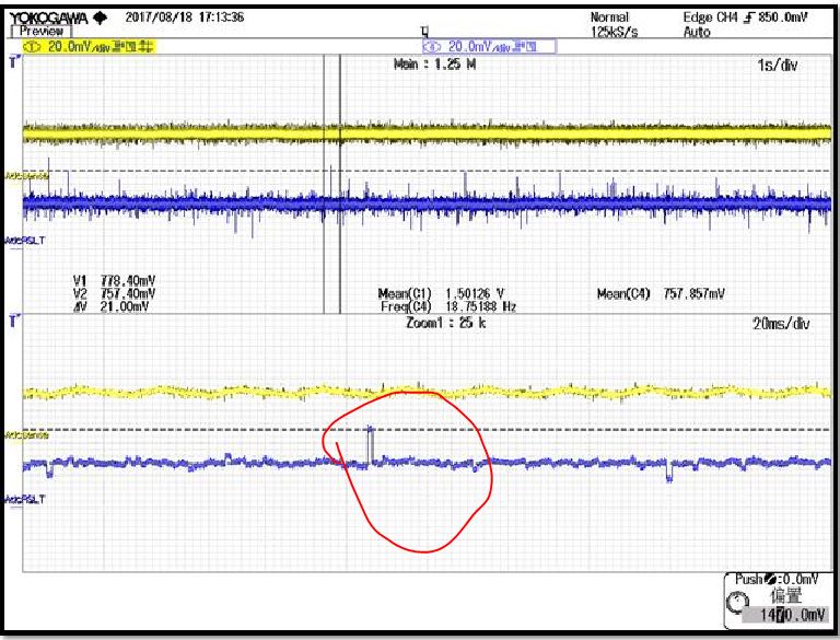
Below is my test code use DAC output ACD sample value, ADCC3 input 1.5V signal.
//#############################################################################
//
// FILE: adc_ex1_soc_epwm.c
//
// TITLE: ADC ePWM Triggering
//
//! \addtogroup bitfield_example_list
//! <h1>ADC ePWM Triggering</h1>
//!
//! This example sets up ePWM1 to periodically trigger a conversion on ADCA.
//!
//! \b External \b Connections \n
//! - A0 should be connected to a signal to convert
//!
//! \b Watch \b Variables \n
//! - \b adcAResults - A sequence of analog-to-digital conversion samples from
//! pin A0. The time between samples is determined based on the period
//! of the ePWM timer.
//!
//
//#############################################################################
// $TI Release: F28004x Support Library v1.00.00.00 $
// $Release Date: Wed Jan 25 16:01:20 CST 2017 $
// $Copyright:
// Copyright (C) 2017 Texas Instruments Incorporated - http://www.ti.com/
//
// Redistribution and use in source and binary forms, with or without
// modification, are permitted provided that the following conditions
// are met:
//
// Redistributions of source code must retain the above copyright
// notice, this list of conditions and the following disclaimer.
//
// Redistributions in binary form must reproduce the above copyright
// notice, this list of conditions and the following disclaimer in the
// documentation and/or other materials provided with the
// distribution.
//
// Neither the name of Texas Instruments Incorporated nor the names of
// its contributors may be used to endorse or promote products derived
// from this software without specific prior written permission.
//
// THIS SOFTWARE IS PROVIDED BY THE COPYRIGHT HOLDERS AND CONTRIBUTORS
// "AS IS" AND ANY EXPRESS OR IMPLIED WARRANTIES, INCLUDING, BUT NOT
// LIMITED TO, THE IMPLIED WARRANTIES OF MERCHANTABILITY AND FITNESS FOR
// A PARTICULAR PURPOSE ARE DISCLAIMED. IN NO EVENT SHALL THE COPYRIGHT
// OWNER OR CONTRIBUTORS BE LIABLE FOR ANY DIRECT, INDIRECT, INCIDENTAL,
// SPECIAL, EXEMPLARY, OR CONSEQUENTIAL DAMAGES (INCLUDING, BUT NOT
// LIMITED TO, PROCUREMENT OF SUBSTITUTE GOODS OR SERVICES; LOSS OF USE,
// DATA, OR PROFITS; OR BUSINESS INTERRUPTION) HOWEVER CAUSED AND ON ANY
// THEORY OF LIABILITY, WHETHER IN CONTRACT, STRICT LIABILITY, OR TORT
// (INCLUDING NEGLIGENCE OR OTHERWISE) ARISING IN ANY WAY OUT OF THE USE
// OF THIS SOFTWARE, EVEN IF ADVISED OF THE POSSIBILITY OF SUCH DAMAGE.
// $
//#############################################################################
//
// Included Files
//
#include "F28x_Project.h"
//
// Defines
//
#define RESULTS_BUFFER_SIZE 256
#define ADC_P12_GAIN 3.3/4095/0.19946809f
//
// Globals
//
uint16_t adcAResults[RESULTS_BUFFER_SIZE]; // Buffer for results
uint16_t index;
uint16_t i = 0;
// Index into result buffer
volatile uint16_t bufferFull; // Flag to indicate buffer is full
//
// Function Prototypes
//
void initADC(void);
void initEPWM(void);
void initADCSOC(void);
void configureDAC(void);
void GetADCRlt(void);
__interrupt void adcA1ISR(void);
//
// Main
//
void main(void)
{
//
// Initialize device clock and peripherals
//
InitSysCtrl();
//
// Initialize GPIO
//
InitGpio();
//
// Disable CPU interrupts
//
DINT;
//
// Initialize the PIE control registers to their default state.
// The default state is all PIE interrupts disabled and flags
// are cleared.
//
InitPieCtrl();
//
// Disable CPU interrupts and clear all CPU interrupt flags:
//
IER = 0x0000;
IFR = 0x0000;
//
// Initialize the PIE vector table with pointers to the shell Interrupt
// Service Routines (ISR).
//
InitPieVectTable();
//
// Map ISR functions
//
EALLOW;
// PieVectTable.ADCA1_INT = &adcA1ISR; // Function for ADCA interrupt 1
EDIS;
//
// Configure the ADC and power it up
//
initADC();
//
// Configure the ePWM
//
initEPWM();
//
// Setup the ADC for ePWM triggered conversions on channel 0
//
initADCSOC();
configureDAC();
//
// Enable global Interrupts and higher priority real-time debug events:
//
// IER |= M_INT1; // Enable group 1 interrupts
EINT; // Enable Global interrupt INTM
ERTM; // Enable Global realtime interrupt DBGM
//
// Initialize results buffer
//
for(index = 0; index < RESULTS_BUFFER_SIZE; index++)
{
adcAResults[index] = 0;
}
index = 0;
bufferFull = 0;
//
// Enable PIE interrupt
//
PieCtrlRegs.PIEIER1.bit.INTx1 = 1;
//
// Sync ePWM
//
EALLOW;
CpuSysRegs.PCLKCR0.bit.TBCLKSYNC = 1;
//
// Take conversions indefinitely in loop
//
while(1)
{
//
// Start ePWM
//
EPwm1Regs.ETSEL.bit.SOCAEN = 1; // Enable SOCA
EPwm1Regs.TBCTL.bit.CTRMODE = 0; // Unfreeze, and enter up count mode
i++;
if(i>10000)
{
GetADCRlt();
i = 0;
}
}
}
//
// initADC - Function to configure and power up ADCA.
//
void initADC(void)
{
//
// Setup VREF as internal
//
SetVREF(ADC_ADCC, ADC_INTERNAL, ADC_VREF2P5);
EALLOW;
//
// Set ADCCLK divider to /4
//
AdccRegs.ADCCTL2.bit.PRESCALE = 6;
//
// Set pulse positions to late
//
AdccRegs.ADCCTL1.bit.INTPULSEPOS = 1;
//
// Power up the ADC and then delay for 1 ms
//
AdccRegs.ADCCTL1.bit.ADCPWDNZ = 1;
EDIS;
DELAY_US(1000);
}
//
// initEPWM - Function to configure ePWM1 to generate the SOC.
//
void initEPWM(void)
{
EALLOW;
EPwm1Regs.ETSEL.bit.SOCAEN = 0; // Disable SOC on A group
EPwm1Regs.ETSEL.bit.SOCASEL = 4; // Select SOC on up-count
EPwm1Regs.ETPS.bit.SOCAPRD = 1; // Generate pulse on 1st event
EPwm1Regs.CMPA.bit.CMPA = 0x0800; // Set compare A value to 2048 counts
EPwm1Regs.TBPRD = 0x1000; // Set period to 4096 counts
EPwm1Regs.TBCTL.bit.CTRMODE = 3; // Freeze counter
EDIS;
}
//
// initADCSOC - Function to configure ADCA's SOC0 to be triggered by ePWM1.
//
void initADCSOC(void)
{
//
// Select the channels to convert and the end of conversion flag
//
EALLOW;
AdccRegs.ADCSOC0CTL.bit.CHSEL = 2; // SOC0 will convert pin A0
AdccRegs.ADCSOC0CTL.bit.ACQPS = 14; // Sample window is 10 SYSCLK cycles
AdccRegs.ADCSOC0CTL.bit.TRIGSEL = 0; // Trigger on ePWM1 SOCA
AdccRegs.ADCSOC2CTL.bit.CHSEL = 3; // SOC0 will convert pin A0
AdccRegs.ADCSOC2CTL.bit.ACQPS = 14; // Sample window is 10 SYSCLK cycles
AdccRegs.ADCSOC2CTL.bit.TRIGSEL = 5; // Trigger on ePWM1 SOCA
AdccRegs.ADCINTSEL1N2.bit.INT1SEL = 0; // End of SOC0 will set INT1 flag
AdccRegs.ADCINTSEL1N2.bit.INT1E = 1; // Enable INT1 flag
AdccRegs.ADCINTFLGCLR.bit.ADCINT1 = 1; // Make sure INT1 flag is cleared
EDIS;
}
//
// adcA1ISR - ADC A Interrupt 1 ISR
//
__interrupt void adcA1ISR(void)
{
//
// Add the latest result to the buffer
//
adcAResults[index++] = AdcaResultRegs.ADCRESULT0;
//
// Set the bufferFull flag if the buffer is full
//
if(RESULTS_BUFFER_SIZE <= index)
{
index = 0;
bufferFull = 1;
}
//
// Clear the interrupt flag and issue ACK
//
AdccRegs.ADCINTFLGCLR.bit.ADCINT1 = 1;
PieCtrlRegs.PIEACK.all = PIEACK_GROUP1;
}
void configureDAC(void)
{
EALLOW;
DacbRegs.DACCTL.bit.LOADMODE = 0;
// DacbRegs.DACCTL.bit.DACREFSEL = 0; //0 VDAC/VSSA are the reference voltages
DacbRegs.DACCTL.bit.DACREFSEL = 1; // 1 ADC VREFHI/VREFLO are the reference voltages
DacbRegs.DACVALS.bit.DACVALS = 0;
DacbRegs.DACOUTEN.bit.DACOUTEN = 1;
EDIS;
F28x_usDelay(10);
}
void GetADCRlt(void)
{
uint32_t P12Volt;
// AdccRegs.ADCSOCFRC1.bit.SOC2 = 1; /* start P12V_SENSE sampling */
P12Volt = AdccResultRegs.ADCRESULT2;
if((P12Volt < 2920) && (P12Volt > 2880))
{
DacbRegs.DACVALS.bit.DACVALS = P12Volt;
}
// else if(P12Volt < 2860)
// {
// DacbRegs.DACVALS.bit.DACVALS = 100;
// }
// else
// {
// DacbRegs.DACVALS.bit.DACVALS = P12Volt;
// }
}
//
// End of File
//
Do you know why will have glitch like that? Worst case, it will have more than 30% failure.
Thanks!
BR
Joe

