This thread has been locked.

If you have a related question, please click the "Ask a related question" button in the top right corner. The newly created question will be automatically linked to this question.

TMS320F28069: F28069, On Chip Debugging, ADC Values

Part Number: TMS320F28069
Other Parts Discussed in Thread: CONTROLSUITE

Hello Friends,

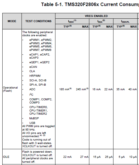
I am trying to debugging on chip f28069 micro controller with emulator. When I run Example_2806xAdcSoc example program which is imported from Resource Library, the AdcResult.ADCRESULT values are getting high to 4095 without applying the adc input voltage (0-3). The input current reading was changed to 0.04A to 0.17A when I flash the micro controller.  Does current value changeswhen flashing the micro controller on target with the help of emulator? I am using XDS100V2 emulator.   Can you please help me out here.

Thanks & Regards,

Ranjit

  • Ranjit,

    I'm having trouble understanding your problem statement and hardware setup.

    Is the problem that the ADC is converting 4095 when the ADC channel is floating? The conversion values are undefined when there is no signal present so 4095 is acceptable.

    Please elaborate on "input current" for your setup. What is the source and destination of that current? How are you reading it? Are you saying that this reading is transitive while the device is flashing or it is static while the device is executing program out of flash?

    -Tommy
  • Hardware setup: I am not using any development board. I have a target board with f28069 micro controller soldered on it. I am using XDS100V2 emulator for flashing and debugging. I have external DC supply to power up the target board.

    Problem:
    I am applying 3.3V input voltage from external DC power supply to f28069 micro controller through connector. Here before flashing the code into the micro controller by using XDS100v2 emulator, the input current reading on the DC source is 0.04A.
    After flashing the code into the micro controller, the current reading is changing into 0.17A. Is it good sign that increasing the current in DC source?
  • Ranjit,

    I don't think that there is anything significant about the increase in current consumption.  It is most likely the difference between the device powering on in a default idle mode vs the post-program state where various modules (such as flash) have been enabled.

    You can see some typical power numbers in the datasheet:

    -Tommy

  • Tommy,

    But my Analog input are not working on my target board. All the ADC values are 4095. I have applied analog input to the ADCINA5 and rest of the analog pins are floating. I have tried giving input to the other ADCIN pins but the result is same. Do I need to activate any register to read the ADC values in CCS?

    - Ranjit
  • Ranjit,

    The examples in ControlSUITE should be initializing everything that is needed. Are you looking at the Voltage1 and Voltage2 array contents?

    You can also try the "adc_temp_sensor_conv" example. This will not require any external voltage signals.

    -Tommy