


Part Number: LAUNCHXL-F28377S
Hello TI community.
My goal is to implement Zero-Current-Switching for a MOSFET device.
If a comparator detects that the current through the switch has fallen below a threshold, the switch has to open.
Additionally I want to ignore the comparator for a certain time afterwards so that the current can rise again in the next switching period. In other words, I want to open the switch only from the moment the comparator perks up until the end of the period.
To program the Launchpad that should realize this mechanic I am using the TI Support Package for Simulink. To make the first tests as easy as possible I used no external signals and let the board generate two synchronized PWMs instead. The power supply is done over USB.
One PWM (PWM2A) is intended as a static switching signal that periodically closes the switch for a long enough time. The other (PWM3A) models the comparator signal that decides when to open it again.
If the comparator signal goes high, the PWM2A should be clamped to low (green curve on the right of the image below).

This clamping action can be done by the Trip-Zone Unit when feeding the comparator signal to a TZ pin (sidenote: the signal has to be inverted because TZ is active-low). But that does not satisfy the additional goal of ignoring the falling edge of the signal.
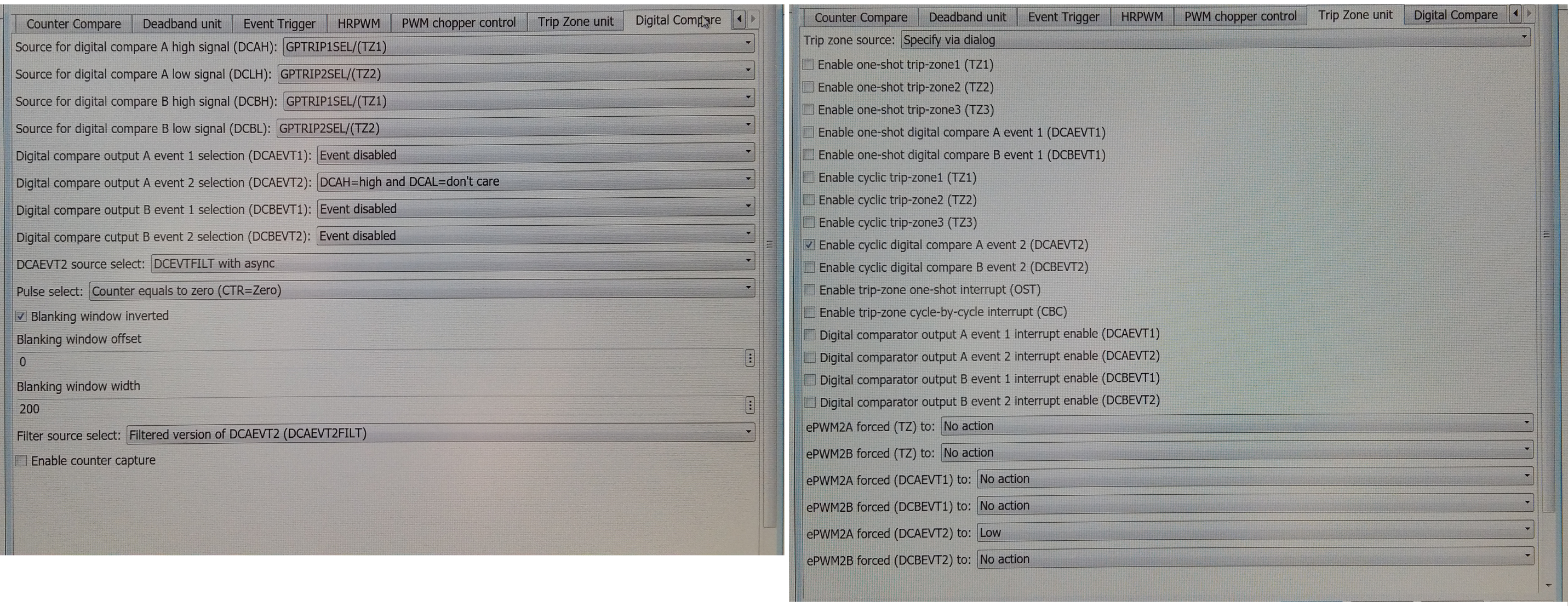
Fittingly I discovered that I could use a Blanking Window when triggering the Trip-Zone Unit via a Digital Compare event. The selected options in the GUI of the Hardware Support Package for Simulink can be seen in the image below. The selection for "Digital compare output A event 2" is basically the same as using TZ1 alone because TZ2 is "don't care". The filter should prevent any action for the first 200 cycles of the period. Only after that can events be generated.
These events are used by the trip-zone module on a "cycle-per-cycle" basis to force the PWM2A output to Low.
The problem is that PWM2A remains unchanged by PWM3A.
I checked that I used the correct pins on the launchpad for the PWM outputs. The pins used for TZ1/2 I defined in the Configuration Parameter Dialog.
ePWM3A is of course connected to TZ1.
Any help is appreciated. Thanks in advance for answers.

