Part Number: TMS320F28335
Tool/software: Code Composer Studio
Hello
I want to read three voltage values with ADC, these values are not in the range of 0-3V so using op-amp, I attenuate them (with factor q) and then add them with a constant voltage (p) to get a voltage in 0-3V and then read this with ADC.
My questions:
1. After reading this value, I subtract the added voltage from the result and then multiply it with q to get my actual voltage. Should I use ADC mirror registers or ADC result registers? So far I have been doing the following code with no result:
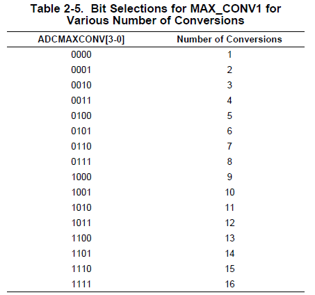
AdcRegs.ADCMAXCONV.all = 0x0003;       // Setup 2 conv's on SEQ1
    AdcRegs.ADCCHSELSEQ1.bit.CONV00 = 0x2; // Setup ADCINA2 as 1st SEQ1 conv.
    AdcRegs.ADCCHSELSEQ1.bit.CONV01 = 0x3; // Setup ADCINA3 as 2nd SEQ1 conv.
    AdcRegs.ADCCHSELSEQ1.bit.CONV02 = 0x4;

AdcRegs.ADCTRL1.bit.ACQ_PS=0x3;
    AdcRegs.ADCTRL2.bit.EPWM_SOCA_SEQ1 = 1;

    AdcRegs.ADCTRL2.bit.INT_ENA_SEQ1 = 1;  // Enable SEQ1 interrupt (every EOS)

EPwm1Regs.ETSEL.bit.SOCAEN = 1;     // Enable SOC on A group
    EPwm1Regs.ETSEL.bit.SOCASEL = 4;    // Select SOC from from CPMA on upcount
    EPwm1Regs.ETPS.bit.SOCAPRD = 1;     // Generate pulse on 1st event
    EPwm1Regs.CMPA.half.CMPA = 0x0080;  // Set compare A value
    EPwm1Regs.TBPRD = 0xC8;           // Set period for ePWM1
    EPwm1Regs.TBCTL.bit.CTRMODE = 0;    // count up and start

__interrupt void
adc_isr(void)
{


#define offset2 0x7BB;


    Voltage1 = AdcMirror.ADCRESULT0-offset1;
    Voltage2 = AdcMirror.ADCRESULT1-offset1;
    Voltage3 = AdcMirror.ADCRESULT2-offset1;

    current = (Voltage1-Voltage2);
    voltage = (Voltage2-Voltage3);


    AdcRegs.ADCTRL2.bit.RST_SEQ1 = 1;         // Reset SEQ1
    AdcRegs.ADCST.bit.INT_SEQ1_CLR = 1;       // Clear INT SEQ1 bit
    PieCtrlRegs.PIEACK.all = PIEACK_GROUP1;   // Acknowledge interrupt to PIE

    return;
}
2. I have defined A2,A3,A4 as my channels and I use them. however when I check the ADC registers, 4 of them has values (ADCRESULT0, ADCRESULT1, ADCRESULT2, ADCRESULT3). Shouldn't it be three registers? I mean how should I read these four registers if I only have 3 channels?
Regards,
Ata