Other Parts Discussed in Thread: CC3200
Tool/software: Code Composer Studio
Hi,
I'm writing a code to communicate through spi mode with a CC3200. F28379D is a slave while CC3200 is a master. So, the master work perfectly, infact it sending a string like this "This is CC3200 SPI Master Application\n\r". The slave is not working as aspected.. I can send and receive only 2 chars. i want to send a data through spi in slave code but is impossibile with this setting.
I create a for cycle, but i thing that the problem is TXBUF, infact i can see that if i try to send more than 2 chars in the txbuf isnt more space to sending that. I tried to shift 8 space in register using <<8.. i tried to send 2 chars using | for connect the buffer space, but the result is the same. no more than 2 chars..
Another issue is a numbers of sending chars, for example, if i would to send 2 chars i can see that in spirxbuf of cc3200 there is a sequence like ABABABABABABABABABAB, until the buffer space of master is full.
Is there a solution for this 2 problems? Thanks a lot for the help.
Slave code:
//###########################################################################
//
// FILE:   Example_2837xDSpi_FFDLB.c
//
// TITLE:  SPI Digital Loop Back program.
//
//! \addtogroup cpu01_example_list
//! <h1>SPI Digital Loop Back (spi_loopback)</h1>
//!
//!  This program uses the internal loop back test mode of the peripheral.
//!  Other then boot mode pin configuration, no other hardware configuration
//!  is required. Interrupts are not used.
//!
//!  A stream of data is sent and then compared to the received stream.
//!  The sent data looks like this: \n
//!  0000 0001 0002 0003 0004 0005 0006 0007 .... FFFE FFFF \n
//!  This pattern is repeated forever.
//!
//!  \b Watch \b Variables \n
//!  - \b sdata - sent data
//!  - \b rdata - received data
//!
//
//###########################################################################
// $TI Release: F2837xD Support Library v200 $
// $Release Date: Tue Jun 21 13:00:02 CDT 2016 $
// $Copyright: Copyright (C) 2013-2016 Texas Instruments Incorporated -
//             http://www.ti.com/ ALL RIGHTS RESERVED $
//###########################################################################

//
// Included Files
//
#include "F28x_Project.h"

//
// Function Prototypes
//
//Code Based off of TMS320F28335 SPI Example

//Device Headerfile and Examples Include File


//Prototype statements for functions found within this file.
void spi_fifo_init(void);
void spi_init(void);

//Global variables (used to read registers)
unsigned char rdata1;
unsigned char rdata2;
unsigned char sdata[5];

void main(void){

   //Initialize System Control:
   //PLL, WatchDog, enable Peripheral Clocks
   //This example function is found in the DSP2833x_SysCtrl.c file.
   InitSysCtrl();

   //Initialize GPIO:
   //This example function is found in the DSP2833x_Gpio.c file and
   //illustrates how to set the GPIO to it's default state.
   //Setup only the GP I/O only for SPI-A functionality
   //This function is found in DSP2833x_Spi.c
   InitSpiaGpio();

   //Clear all interrupts and initialize PIE vector table:
   //Disable CPU interrupts
   DINT;

   //Initialize PIE control registers to their default state.
   //The default state is all PIE interrupts disabled and flags
   //are cleared.
   //This function is found in the DSP2833x_PieCtrl.c file.
   InitPieCtrl();

   //Disable CPU interrupts and clear all CPU interrupt flags:
   IER = 0x0000;
   IFR = 0x0000;

   //Initialize the PIE vector table with pointers to the shell Interrupt
   //Service Routines (ISR).
   //This will populate the entire table, even if the interrupt
   //is not used in this example.  This is useful for debug purposes.
   //The shell ISR routines are found in DSP2833x_DefaultIsr.c.
   //This function is found in DSP2833x_PieVect.c.
   InitPieVectTable();

   spi_fifo_init();   // Initialize the Spi FIFO
   spi_init();        // init SPI

   //User specific code:
   //Interrupts are not used in this example.
   for(;;)
   {
       //Wait until data is received
       while(SpiaRegs.SPIFFRX.bit.RXFFST !=1) { }
       rdata1 = SpiaRegs.SPIRXBUF & 0xFF;
       rdata2 = (SpiaRegs.SPIRXBUF & 0xFF00) >> 8;
     //Load Transfer Buffer
       int i=0;
       for(i=0;i<4; i++){
       sdata[0] = 'f';
     SpiaRegs.SPITXBUF = sdata[0];
     sdata[1] = 'u';
     SpiaRegs.SPITXBUF = sdata[1]<<8;
     sdata[2] = 'n';
     sdata[3] = 'g';
     SpiaRegs.SPITXBUF = (sdata[2]<<8) | (sdata[3]<<8);


     i=0;

       }


     /* Report the sensor data */

     //character generator
     //if(sdata[0]==67){sdata[0] = 'D';}
     //else{sdata[0] = 'C';}
     //if(sdata[1]==68){sdata[1] = 'C';}
    //else{sdata[1] = 'D';}


   }
}

void spi_init(){

   //SPICCR is a 8 bit register
   //Bit 7 (Software Reset): Set to 0, must be cleared before configuration
   //Bit 6 (Clock Polarity): Set to 0, data outputted on rising edge and data incoming is falling edge
   //Bit 5 (Reserved): No writing allowed
   //Bit 4 (SPI Loopback): Set to 0 to disable, only for internal test only
   //Bit 3-0 (Character length bits): Set to 0b1111 for 16 bit character (CC3200 is sending two character totaling 16 bits)
   //SpiaRegs.SPICCR.all =0x008F;

   SpiaRegs.SPICCR.bit.SPISWRESET = 0;
   SpiaRegs.SPICCR.bit.CLKPOLARITY = 0;
   SpiaRegs.SPICCR.bit.SPICHAR = 0xf; //7 bit
   SpiaRegs.SPICCR.bit.SPISWRESET = 1;

   SpiaRegs.SPICTL.bit.CLK_PHASE = 1;
   SpiaRegs.SPICTL.bit.TALK = 1;
   SpiaRegs.SPICTL.bit.SPIINTENA = 1;
   SpiaRegs.SPICTL.bit.MASTER_SLAVE = 0; //Slave

   SpiaRegs.SPISTS.bit.INT_FLAG = 0;
   SpiaRegs.SPISTS.bit.OVERRUN_FLAG = 0;


   CpuSysRegs.PCLKCR8.bit.SPI_A = 1;


   //SPICTL is a 8 bit register
   //Bit 7-5 (Reserved): No writing allowed
   //Bit 4 (Overrun Interrupt Enable): Set to 0 for the time being, just trying to do a simple SPI connection
   //Bit 3 (Clock Phase): Set to 0, normal SPI clocking scheme (without being delayed one-half cycle)
   //Bit 2 (Master/Slave bit): Set to 0 to be the slave
   //Bit 1 (Talk bit): Set to 1, trying to send data back
   //Bit 0 (SPI Interrupt Enable): Set to 0, not worried about interrupts right now
   //SpiaRegs.SPICTL.all =0x0002; //commentato 31 agosto

   //This register does not matter since clock is coming from CC3200-LAUNCHXL
   SpiaRegs.SPIBRR =0x007F; //era 0x000F

   //SPICCR is a 8 bit register
   //Bit 7 (Software Reset): Set to 1, must be set when ready for data transmission
   //Bit 6 (Clock Polarity): Set to 0, data outputted on rising edge and data incoming is falling edge
   //Bit 5 (Reserved): No writing allowed
   //Bit 4 (SPI Loopback): Set to 0 to disable, only for internal test only
   //Bit 3-0 (Character length bits): Set to 0b1111 for 16 bit character (CC3200 is sending two character totaling 16 bits)
   //SpiaRegs.SPICCR.all =0x008F; //commentato 31 agosto

   //Set so breakpoints don't disturb transmission
   SpiaRegs.SPIPRI.bit.FREE = 1;
}

void spi_fifo_init(){

   //Initialize SPI FIFO registers
   SpiaRegs.SPIFFTX.all=0xE040;
   SpiaRegs.SPIFFRX.all=0x204f;
   SpiaRegs.SPIFFCT.all=0x0;
}
Master code:
//Code is based off of "SPI Demo" that came with the CC3200-LAUNCHXL board

//Standard Includes
#include <string.h>

//Driver Library Includes
#include "hw_types.h"
#include "hw_memmap.h"
#include "hw_common_reg.h"
#include "hw_ints.h"
#include "spi.h"
#include "rom.h"
#include "rom_map.h"
#include "utils.h"
#include "prcm.h"
#include "uart.h"
#include "interrupt.h"

//Common Interface Includes
#include "uart_if.h"
#include "pinmux.h"
//Character generator variable
   char character1 = '0';
   char character2 = '0';

//Useful Macros
#define SPI_IF_BIT_RATE  100000 //in bits per second (bps)
#define TR_BUFF_SIZE     50
#define MASTER_MSG       "This is CC3200 SPI Master Application\n\r"

//*****Start of Global Variables*****
static unsigned char g_ucTxBuff[TR_BUFF_SIZE];
static unsigned char g_ucRxBuff[TR_BUFF_SIZE];


//Not too sure what this stuff does here, but came with SPI example
#if defined(ccs)
extern void (* const g_pfnVectors[])(void);
#endif
#if defined(ewarm)
extern uVectorEntry __vector_table;
#endif
//*****End of Global Variables*****

//*****Start of Board Initialization & Configuration***** (Came with SPI Demo as well)
static void
BoardInit(void)
{
/* In case of TI-RTOS vector table is initialize by OS itself */
#ifndef USE_TIRTOS
  //
  // Set vector table base
  //
#if defined(ccs)
    MAP_IntVTableBaseSet((unsigned long)&g_pfnVectors[0]);
#endif
#if defined(ewarm)
    MAP_IntVTableBaseSet((unsigned long)&__vector_table);
#endif
#endif
    //
    // Enable Processor
    //
    MAP_IntMasterEnable();
    MAP_IntEnable(FAULT_SYSTICK);

    PRCMCC3200MCUInit();
}
//*****End of Board Initialization & Configuration*****

void main(){

    memcpy(g_ucTxBuff,MASTER_MSG,sizeof(MASTER_MSG));

   //Initialize Board Configurations
   BoardInit();

   //Muxing UART and SPI Lines
   //All this does is configure pins for MOSI, MISO, Chip Select, and Clock.
   PinMuxConfig();

   //Enable the SPI Module Clock
   //Enables clock to peripheral
   //PRCM_GSPI = Macro for the SPI Peripheral (0x00000003)
   //PRCM_RUN_MODE_CLK = Ungates clock to the peripheral (could also be PRCM_SLP_MODE_CLK
   //which keeps the clocks ungated in sleep)
   MAP_PRCMPeripheralClkEnable(PRCM_GSPI,PRCM_RUN_MODE_CLK);

   //Reset the Peripheral
   //PRCM_GSPI = Macro for the SPI Peripheral (resets the SPI Peripheral)
   MAP_PRCMPeripheralReset(PRCM_GSPI);

   //Reset SPI
   //Performs a software reset to the SPI Module
   //GSPI_BASE = Macro for the SPI Base Address (0x44021000)
   MAP_SPIReset(GSPI_BASE);

   //Configure SPI Interface (all values are MACROS)
   //1st argument is base address of SPI Module (which is GSPI_BASE)
   //2nd argument is rate of clock being supplied to SPI Module
   //3rd argument is the desired bit rate (which is defined in the "useful macro" section above)
   //4th argument is SPI_MODE_MASTER, which configures board as the master
   //5th argument is SPI_SUB_MODE_0, which sets clock polarity and phase to 0
   //6th argument is logical OR combination, which sets chip select to be controlled by software (SPI_SW_CTRL_CS),
   //sets module to 4 pin mode (SPI_4PIN_MODE), sets turbo mode off (SPI_TURBO_OFF) and I have no idea what turbo mode is,
   //sets chip select to be active low (SPI_CS_ACTIVELOW), and sets the bit length to 16 bits, or 2 characters (SPI_WL_16)
   MAP_SPIConfigSetExpClk(GSPI_BASE,MAP_PRCMPeripheralClockGet(PRCM_GSPI),SPI_IF_BIT_RATE,SPI_MODE_MASTER,SPI_SUB_MODE_1,
   (SPI_SW_CTRL_CS |
   SPI_4PIN_MODE |
   SPI_TURBO_OFF |
   SPI_CS_ACTIVELOW |
   SPI_WL_8));

   //Enable SPI for Communication
   //GSPI_BASE = Macro for the SPI Base Address (0x44021000)
   MAP_SPIEnable(GSPI_BASE);

   while(1){
   //Load two 8 bit characters into transfer buffer
   //g_ucTxBuff[0] = 'A';

   //Send characters over MOSI pin
   //1st argument is base address of SPI Module (GSPI_BASE)
   //2nd argument is pointer to transfer buffer (g_ucTxBuff)
   //3rd argument is pointer to receive buffer (g_ucRxBuff)
   //4th argument is size of data in bytes (1 byte = 8 bits)
   //5th argument is logical OR that enable chip select pin before transmission,
   //and disables chip select pin after transmission (SPI_CS_ENABLE|SPI_CS_DISABLE)
   MAP_SPITransfer(GSPI_BASE,g_ucTxBuff,g_ucRxBuff,50,SPI_CS_ENABLE|SPI_CS_DISABLE);

   //int number = (int)strtol(g_ucRxBuff, NULL, 16);

   //character generator
   //if(character1==65){character1 = '5';}
   //else{character1 = '5';}
   //if(character2==66){character2 = '5';}
   //else{character2 = '5';}
   UtilsDelay(100000);
   }
   //while(1){}
}
Image of TXBUF of CC3200:

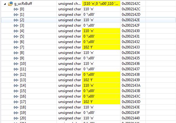
Image of RXBUFF CC3200 (Data coming from F28379D):