This thread has been locked.

If you have a related question, please click the "Ask a related question" button in the top right corner. The newly created question will be automatically linked to this question.

CCS/TMS320F28379D: How i can shift TXBUF register for sending more than 2 chars using spi

Part Number: TMS320F28379D
Other Parts Discussed in Thread: CC3200

Tool/software: Code Composer Studio

Hi,

I posted a question about sending more than 2 chars through spi using F28379D, so, i check and modify every single bit of all registers for understand where i can fall in error. But after that i can tell you that the setting is right. My fault is in Code Sketch, infact i can send 2 chars but i have really problem to shift the TXBUFF after this 2 chars. How i can write in the sketch to wait until my BUFFULL_FLAG is full? , i need to wait until this Buff is completly full with my chars.

Another question regarding C++ Language used for TI Sketch. In another post i saw this command :  SpiaRegs.SPITXBUF =sdata[0] | sdata[1]<<8;

While  sdata[0] ='A'; and  sdata[1] ='B'; 

and it work, but only for 2 chars.

I tried to create a for cycle using int i=0; and SpiaRegs.SPITXBUF=sdata[i] and incremente i++,  but how i said the problem is in the shift, the result is the only last char sent.

My objective is to sent a string of chars, for example to response at my CC3200 : "This is F28379D Slave Application"  or send an ADC samples.

Any help would be appreciated !! Thanks, Alessio

  • Your description of what you want to do with the BUFFULL_FLAG doesn't seem to match the actual functionality of the flag. The flag is supposed to get set when a character is written to the transmit buffer. It's more likely that you would want to wait until the BUFFULL_FLAG is cleared before writing characters to the buffer. You can wait for the BUFFULL_FLAG to clear by using something like while(SpiaRegs.SPISTS.bit.BUFFULL_FLAG == 1);

    SpiaRegs.SPITXBUF is a 16-bit register, so there is only room in the register for two 8-bit words at a time. If you want to send them two at a time like that, your loop could increment by 2, write sdata[i] | (sdata[i+1]<<8), and wait for the BUFFULL_FLAG to clear before writing another two characters.

    Or if you want to send the characters one at the time you could change your character size to 8 (SPICHAR field in the SPICCR register) and write sdata[i]<<8 to the TXBUF register. Note that you have to left shift the data when your character size is less than 16.

    Whitney

  • Hi  Whitney,

    Thank you for replace and your attention !

    I followed your suggestions and i can see a better improvement ! Infact a slave send the string with a little bit confution, I'm going to explain. 

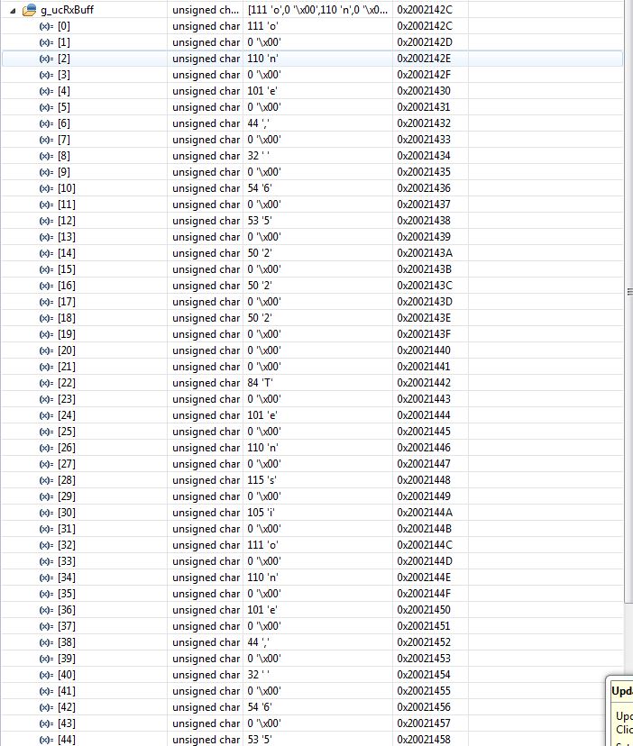
    The Slave message is "Tensione, 65222" and the master receive a message like this: 

    As you can see the message is correct but there is a 0 bit between the packets and continue transaction. If at this moment x(0)= 111 the next step x(2)= 111, while i'm trying to have a stationary message without bit of 0 and, like this (master message) :

    Here a new sketch with your suggestions 

    //###########################################################################
    //
    // FILE:   Example_2837xDSpi_FFDLB.c
    //
    // TITLE:  SPI Digital Loop Back program.
    //
    //! \addtogroup cpu01_example_list
    //! <h1>SPI Digital Loop Back (spi_loopback)</h1>
    //!
    //!  This program uses the internal loop back test mode of the peripheral.
    //!  Other then boot mode pin configuration, no other hardware configuration
    //!  is required. Interrupts are not used.
    //!
    //!  A stream of data is sent and then compared to the received stream.
    //!  The sent data looks like this: \n
    //!  0000 0001 0002 0003 0004 0005 0006 0007 .... FFFE FFFF \n
    //!  This pattern is repeated forever.
    //!
    //!  \b Watch \b Variables \n
    //!  - \b sdata - sent data
    //!  - \b rdata - received data
    //!
    //
    //###########################################################################
    // $TI Release: F2837xD Support Library v200 $
    // $Release Date: Tue Jun 21 13:00:02 CDT 2016 $
    // $Copyright: Copyright (C) 2013-2016 Texas Instruments Incorporated -
    //             http://www.ti.com/ ALL RIGHTS RESERVED $
    //###########################################################################
    
    //
    // Included Files
    //
    #include "F28x_Project.h"
    #include "stdio.h"
    //
    // Function Prototypes
    //
    //Code Based off of TMS320F28335 SPI Example
    
    //Device Headerfile and Examples Include File
    
    
    //Prototype statements for functions found within this file.
    void FIFO_init(void);
    void spi_init(void);
    void spi_xmit(Uint16 a);
    void delay_loop(void);
    Uint16 temp=65222;
    Uint16 Txbuffer1;
    Uint16 Txbuffer2;
    
    //Global variables (used to read registers)
    unsigned char rdata;
    unsigned char rdata1;
    unsigned char rdata2;
    unsigned char sdata[16];
    
    void delay_loop()
    {
        long i;
        for (i = 0; i < 15000; i++) {}
    }
    void main(void){
    
       //Initialize System Control:
       //PLL, WatchDog, enable Peripheral Clocks
       //This example function is found in the DSP2833x_SysCtrl.c file.
       InitSysCtrl();
    
       //Initialize GPIO:
       //This example function is found in the DSP2833x_Gpio.c file and
       //illustrates how to set the GPIO to it's default state.
       //Setup only the GP I/O only for SPI-A functionality
       //This function is found in DSP2833x_Spi.c
       InitSpiaGpio();
    
       //Clear all interrupts and initialize PIE vector table:
       //Disable CPU interrupts
       DINT;
    
       //Initialize PIE control registers to their default state.
       //The default state is all PIE interrupts disabled and flags
       //are cleared.
       //This function is found in the DSP2833x_PieCtrl.c file.
       InitPieCtrl();
    
       //Disable CPU interrupts and clear all CPU interrupt flags:
       IER = 0x0000;
       IFR = 0x0000;
    
       //Initialize the PIE vector table with pointers to the shell Interrupt
       //Service Routines (ISR).
       //This will populate the entire table, even if the interrupt
       //is not used in this example.  This is useful for debug purposes.
       //The shell ISR routines are found in DSP2833x_DefaultIsr.c.
       //This function is found in DSP2833x_PieVect.c.
       InitPieVectTable();
    
       FIFO_init();   // Initialize the Spi FIFO
       spi_init();        // init SPI
    
       //User specific code:
       //Interrupts are not used in this example.
       for(;;)
       {
           //Wait until data is received
           while(SpiaRegs.SPIFFRX.bit.RXFFST !=1) { }
           rdata1 = SpiaRegs.SPIRXBUF & 0xFF;
           rdata2 = (SpiaRegs.SPIRXBUF & 0xFF00) >> 8;
         //Load Transfer Buffer
           int i=0;
    //for (i=0; i<4; i++){
        /*char test;
        test=sdata[i]<<8;  */
    
    
           while (i<16) {
                //
                // Transmit data
                //
                spi_xmit(sdata);
    
                //
                // Wait until data is received
                //
                while(SpiaRegs.SPIFFRX.bit.RXFFST !=1) { }
    
                //
                // Check against sent data
                //
                rdata = SpiaRegs.SPIRXBUF;
                uint16_t Length = sprintf(sdata,"Tensione, %u", temp);
               // sdata[i]
                Txbuffer1= sdata[i];                    // | (sdata[i+1]<<8)
                //Txbuffer2= sdata[i+1];
                i++;
                      if (i==16){i=0;}
           }
         //SpiaRegs.SPITXBUF =sdata[1] |sdata[2] |sdata[3] | sdata[4];
        /* SpiaRegs.SPITXBUF= sdata[2];
         SpiaRegs.SPITXBUF= sdata[3];
         SpiaRegs.SPITXBUF= sdata[4];


    //}
    
         sdata[0] ='A';
         sdata[1] = 'B';
         sdata[2] = 'C';


         /* Report the sensor data */
    
         //character generator
         //if(sdata[0]==67){sdata[0] = 'D';}
         //else{sdata[0] = 'C';}
         //if(sdata[1]==68){sdata[1] = 'C';}
        //else{sdata[1] = 'D';}
    
    
       }
    }
    
    void spi_xmit(Uint16 a)
    {
        
            SpiaRegs.SPITXBUF = Txbuffer1 |(Txbuffer2<<8);
    
    
    }
    
    void spi_init(){


       SpiaRegs.SPICCR.bit.SPISWRESET = 0;
       // SpiaRegs.SPISTS.bit.OVERRUN_FLAG = 0; si resetta già con SPISWRESET
       // SpiaRegs.SPISTS.bit.INT_FLAG = 0; si resetta sempre con SPISWRESET
       //(se lo si vuole leggere =0 quando non ha parole da trasmettere o ricevere =1 quando l'SPI ha completato invio/ricezione
       //SpiaRegs.SPISTS.bit.BUFFULL_FLAG =0; Si resetta con SPISWRESET da leggere: 0 Transmit buffer non è pieno =1 è pieno
       // SpiaRegs.SPIBRR= Non va settato in quanto essendo Slave mode non ha nessun effetto
    
       SpiaRegs.SPICTL.bit.MASTER_SLAVE = 0; //Slave
       SpiaRegs.SPICCR.bit.HS_MODE= 0; // HS_disabled; altrimenti =1 HS enabled
       SpiaRegs.SPICCR.bit.CLKPOLARITY = 0; //Data is output on falling edge and input on rising edge
       SpiaRegs.SPICCR.bit.SPICHAR = (16-1); //16 bit altrimenti 0x7 per 7 bit
       SpiaRegs.SPICTL.bit.CLK_PHASE = 0;
       SpiaRegs.SPICCR.bit.SPILBK= 0; // Loopback mode disabled
       SpiaRegs.SPICTL.bit.TALK = 1; //Enables transmission for 4 pin option
       SpiaRegs.SPISTS.bit.OVERRUN_FLAG= 1; //Clear this buff
       // SpiaRegs.SPISTS.bit.INT_FLAG =0x1; //Clear this buff (Basta leggere RXBUFF)
       SpiaRegs.SPICTL.bit.OVERRUNINTENA= 1; //enable receiver_overrun interrupts
       SpiaRegs.SPICTL.bit.SPIINTENA = 0; //Enables the interrupt.
       SpiaRegs.SPICCR.bit.SPISWRESET = 1; //Rilascio reset
       SpiaRegs.SPIPRI.bit.FREE = 1;
      // CpuSysRegs.PCLKCR8.bit.SPI_A = 1; a che serve?!
    }
    void FIFO_init (){
       /******************* SPI FIFO TX BUFF ***********************/
       SpiaRegs.SPIFFTX.bit.SPIRST= 0; //inizializza reset SPI
       SpiaRegs.SPIFFTX.bit.SPIFFENA= 1; // SPI FIFO enhancements are enabled.
       SpiaRegs.SPIFFTX.bit.TXFIFO= 0;  //inizializza reset FIFO
       // SpiaRegs.SPIFFTX.bit.TXFFST= (READ BUFF)
       SpiaRegs.SPIFFTX.bit.TXFFINTCLR= 1; // clear SPIFFTX
       SpiaRegs.SPIFFTX.bit.TXFFIENA= 1; // TX FIFO interrupt based on TXFFIL will be enabled.
       SpiaRegs.SPIFFTX.bit.TXFFIL=7;
       SpiaRegs.SPIFFTX.bit.TXFIFO= 1;
       SpiaRegs.SPIFFTX.bit.SPIRST= 1;
    
    
       /******************* SPI FIFO RX BUFF ***********************/
    
       //SpiaRegs.SPIFFRX.bit.RXFFOVF= READ ONLY
       SpiaRegs.SPIFFRX.bit.RXFFOVFCLR= 1; //Clear SPIFFRX BUFF
       SpiaRegs.SPIFFRX.bit.RXFIFORESET= 0;
       SpiaRegs.SPIFFRX.bit.RXFFINTCLR= 1; //clear SPIFFRX Flag
       SpiaRegs.SPIFFRX.bit.RXFFIENA= 1; // RX FIFO interrupt base on RXFFIL will be enabled.
       SpiaRegs.SPIFFRX.bit.RXFFIL=  16; // RX FIFO interrup request is generated when there are 16 words in the RX Buffer
       SpiaRegs.SPIFFRX.bit.RXFIFORESET= 1;
    
    
       /*********************SPI FIFO Control Register**************************/
       SpiaRegs.SPIFFCT.bit.TXDLY= 0; // The next word in the tx fifo buffer is transferred to previous word
    
       /*********************SPI Priority Control Register***********************/
       SpiaRegs.SPIPRI.bit.STEINV= 0; // SPISTEn is active low (normal)
    
    
    }


    at least my questions are :

    Is correct this command for send correctly as you said?

     SpiaRegs.SPITXBUF = Txbuffer1 |(Txbuffer2<<8);

    where i wrong when the in master message i see the packets shift and consequently a non stable image?

    Thanks, Alessio
  • Hi Alessio,

    In the code you shared you have the line where you assign a value to Txbuffer2 commented out. Does it still not work when you uncomment the line where you write to Txbuffer2 and change i++ to i+=2?

    Whitney