Part Number: TMS320F28377S
Hello Guys,
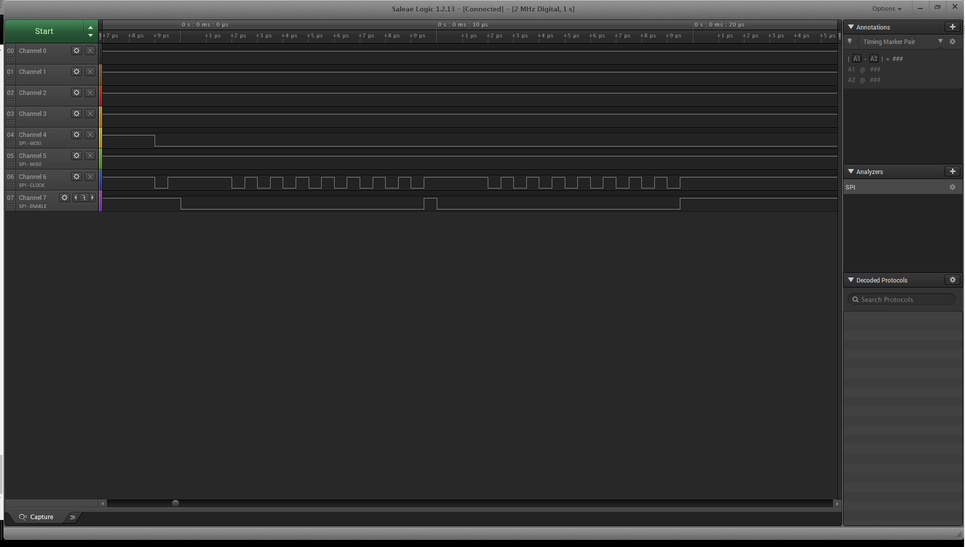
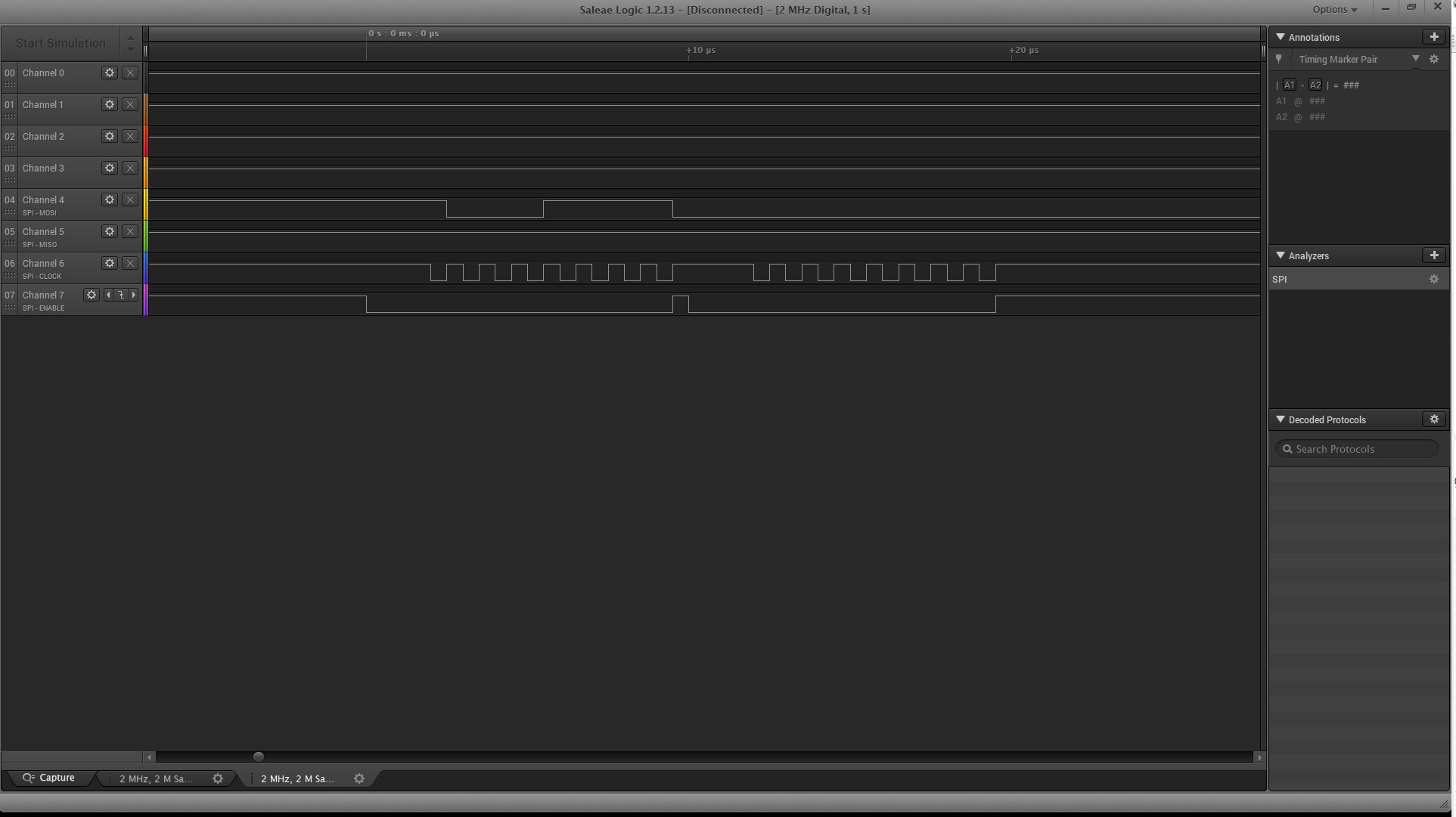
I am trying to interface TI TMS320F28377 LaunchPad with an accelerometer, and this is my first hands-on experience with this set of hardware. I am using SPI-B. With reference to examples given in ControlSuite, I have written the basic code and I have hooked up the logic analyzer to watch the communication. The code executes and I can see communication going on. But logic analyzer is not able to decode the communication for me. InitSysCtrl() sets my system clock to 200Mhz whereas my accelerometer operates as 10Mhz over SPI lines. And then I am just trying to transmit some test data over SPI-B. I am not sure if I have use to use FIFO. Thanks in advance.
//###########################################################################
//
// FILE:    main.c
//
//###########################################################################

// Included Files
#include <stdio.h>

#include "F28x_Project.h"
#include "F2837xS_Examples.h"

// defines
#define SPI_TIMEOUT     1000

/*
 * @brief   Initialize SPI-B GPIOs for accelerometer
 * @param   none
 * @return  none
 */
void spi_b_gpio_init (void)
{
    EALLOW;

    // Enable internal pull-up for the selected pins
    GpioCtrlRegs.GPBPUD.bit.GPIO58 = 0; // Enable pull-up on SPI CLK B
    GpioCtrlRegs.GPBPUD.bit.GPIO59 = 0; // Enable pull-up on SPI STE B
    GpioCtrlRegs.GPBPUD.bit.GPIO60 = 0; // Enable pull-up on SPI SIMO B
    GpioCtrlRegs.GPBPUD.bit.GPIO61 = 0; // Enable pull-up on SPI SOMI B

    // Set qualification for selected pins to asynch only
    GpioCtrlRegs.GPBQSEL2.bit.GPIO58 = 3; // Asynch input SPI CLK B
    GpioCtrlRegs.GPBQSEL2.bit.GPIO59 = 3; // Asynch input SPI STE B
    GpioCtrlRegs.GPBQSEL2.bit.GPIO60 = 3; // Asynch input SPI SIMO B
    GpioCtrlRegs.GPBQSEL2.bit.GPIO61 = 3; // Asynch input SPI SOMI B

    // Configure group MUX
    GpioCtrlRegs.GPBGMUX2.bit.GPIO58 = 1;
    GpioCtrlRegs.GPBGMUX2.bit.GPIO59 = 1;
    GpioCtrlRegs.GPBGMUX2.bit.GPIO60 = 1;
    GpioCtrlRegs.GPBGMUX2.bit.GPIO61 = 1;

    // Configure SPI-B pins using GPIO registers
    GpioCtrlRegs.GPBMUX2.bit.GPIO58 = 2; // Configure as SPI CLK B
    GpioCtrlRegs.GPBMUX2.bit.GPIO59 = 2; // Configure as SPI STE B
    GpioCtrlRegs.GPBMUX2.bit.GPIO60 = 2; // Configure as SPI SIMO B
    GpioCtrlRegs.GPBMUX2.bit.GPIO61 = 2; // Configure as SPI SOMI B

    EDIS;
}

/*
 * @brief   This function initializes the SPI-B to a known state
 * @param   none
 * @return  none
 */
void spi_b_init (void)
{
    // Set reset low before configuration changes
    SpibRegs.SPICCR.bit.SPISWRESET = 0;

    SpibRegs.SPICCR.bit.CLKPOLARITY = 1;    // Clock polarity (1 == falling)
    SpibRegs.SPICCR.bit.SPICHAR = (8-1);    // 8-bit character

    SpibRegs.SPICTL.bit.CLK_PHASE = 1;      // Clock phase (1 == delayed)
    SpibRegs.SPICTL.bit.MASTER_SLAVE = 1;   // Enable master (1 == master)
    SpibRegs.SPICTL.bit.TALK = 1;           // Enable transmission (Talk)
    SpibRegs.SPICTL.bit.SPIINTENA = 0;      // SPI interrupts are disabled

    // Set the baud rate
    // CPU CLK freq = 200 MHz, SPI CLK freq = 1MHz
    // LSPCLK freq  = CPU freq / 4  (by default)
    // BRR          = (LSPCLK freq / SPI CLK freq) - 1
    SpibRegs.SPIBRR.bit.SPI_BIT_RATE = ((200E6 / 4) / 10E5) - 1;

    // Halting on a breakpoint will not halt the SPI
    SpibRegs.SPIPRI.bit.FREE = 1;           // Set FREE bit

    // Release the SPI from reset
    SpibRegs.SPICCR.bit.SPISWRESET = 1;
}

/*
 * @brief   main function
 * @param   none
 * @return  none
 */
void main (void)
{
    /*
     * Initialize System Control:
     * PLL, WatchDog, enable Peripheral Clocks
     * This example function is found in the F2837xS_SysCtrl.c file.
     */
    InitSysCtrl();

    // Initialize GPIO:
    InitGpio();

    spi_b_gpio_init();

    /*
     * Clear all interrupts and initialize PIE vector table:
     * Disable CPU interrupts
     */
    DINT;

    /*
     * Initialize the PIE control registers to their default state.
     * The default state is all PIE interrupts disabled and flags
     * are cleared.
     * This function is found in the F2837xS_PieCtrl.c file.
     */
    InitPieCtrl();

    // Disable CPU interrupts and clear all CPU interrupt flags:
    IER = 0x0000;
    IFR = 0x0000;

    /*
     * Initialize the PIE vector table with pointers to the shell Interrupt
     * Service Routines (ISR).
     * This will populate the entire table, even if the interrupt
     * is not used in this example.  This is useful for debug purposes.
     * The shell ISR routines are found in F2837xS_DefaultIsr.c.
     * This function is found in F2837xS_PieVect.c.
     */
    InitPieVectTable();

    // Enable global Interrupts and higher priority real-time debug events:
    EINT;  // Enable Global interrupt INTM
    ERTM;  // Enable Global real time interrupt DBGM

    // Initialize the Device Peripherals:
    spi_b_init();

    Uint16 spi_timeout = SPI_TIMEOUT;

    SpibRegs.SPITXBUF = 0x0F | 0x80;               // Transmit Buffer

    while ((SpibRegs.SPISTS.bit.INT_FLAG != 1)  && (spi_timeout > 0u))
    {
        // Wait until character has been transferred
        spi_timeout--;
    }

    if(spi_timeout == 0u)
    {
        puts("spi_timeout 1 \n");
    }

    spi_timeout = SPI_TIMEOUT;

    SpibRegs.SPITXBUF = 0x00;               // Transmit Buffer

    while ((SpibRegs.SPISTS.bit.INT_FLAG != 1)  && (spi_timeout > 0u))
    {
        // Wait until character has been transferred
        spi_timeout--;
    }

    Uint16 rdata = SpibRegs.SPIRXBUF;

    return;
}

// End of file