Tool/software: Code Composer Studio
Hello
I am having a problem with triggering ADCINT2.
I was able to implement ADCINT1 without a lot of troubles but the second one does not seem to work.
So here's what I did:
PieVectTable.ADCA2_INT = &adca2_isr;
(I think the above lines links the Pievectortable to the name of the interrupt)
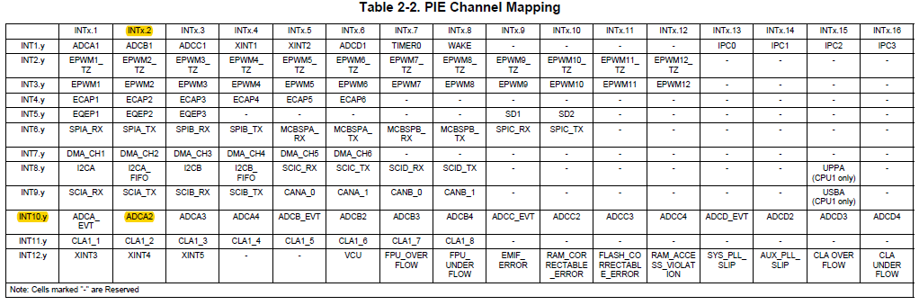
PieCtrlRegs.PIEIER1.bit.INTx2 = 1; //enable interrupt INT1.2 in the PIE Interrupt Assignment Table
IER |= 0x01; // Enable interrupt 1
(I think I only use INT1 of the core and ADCINT1 and ADCINT2 are connected to this one via the PIE)
EINT; // Enable Global interrupt INTM
ERTM; // Enable Global realtime interrupt DBGM
Now say that the end of conversion3 calls ADCINT2 (the ADC does work and stores the result in the third result register)
AdcaRegs.ADCINTSEL1N2.bit.INT2SEL = 0x03; //EOC3 will set ADCINT2 flag - See page 1317/2472 in technical manual
AdcaRegs.ADCINTSEL1N2.bit.INT2E = 1; //enable ADCINT2
AdcaRegs.ADCINTFLGCLR.bit.ADCINT2 = 1; //make sure INT2 flag is cleared - a 1 clears the flag bit
and below you can see the code for the interrupt itself:
interrupt void adca2_isr(void)
{ // This is interrupt INT2 from ADCa
// this interrupt is generated from ADCa EOC3 and only runs at low frequency (e.g. 10Hz)
//First update resultsIndex
if(resultsIndex2 > (RESULTS_BUFFER_SIZE-1))
{
resultsIndex2 = 0;
}
else {resultsIndex2++;}
resultsIndex2++;
test = test-1;
// First do the processing of the measurements
I_PV[resultsIndex2] = (AdcaResultRegs.ADCRESULT3 - OFFSET_I0)*I0_CONV_RATIO; // For the moment we assume that all the conversions are the same but this might not be the case if different sensors are used
V_PV[resultsIndex2] = (AdcbResultRegs.ADCRESULT3 - OFFSET_I1)*V_CONV_RATIO;
//Depending on the measurements, here some more processing might be needed
// Maximum Power Point Tracker - Perturb & Observe algorithm
if(enable_MPPT == 1)
{
V_new = V_PV_meas;
I_new = I_PV_meas;
P_new = V_new*I_new;
dV = V_new - V_old;
dI = I_new - I_old;
dP = P_new - P_old;
if(dP > 0)
{
if(dV < 0)
{I_ref = I_ref_old + I_step;}
else
{I_ref = I_ref_old - I_step;}
}
else
{
if(dV < 0)
{I_ref = I_ref_old - I_step;}
else
{I_ref = I_ref_old + I_step;}
}
//Hier nog eventueel stroomlimieten toevoegen
V_old = V_new;
I_old = I_new;
P_old = P_new;
I_ref_old = I_ref;
}
AdcaRegs.ADCINTFLGCLR.bit.ADCINT2 = 1; //clear INT2 flag
PieCtrlRegs.PIEACK.all = PIEACK_GROUP1;
}
I don't really see what I am doing wrong here. Am I forgetting something? I think I used exactly the same method to set up ADCINT1 and this one works perfectly.
If you would need my entire code, I can upload it as well :)
Kind regards