


Other Parts Discussed in Thread: CONTROLSUITE
Tool/software: Code Composer Studio
Hello all,
I need to ask about the graphic I have added below.
I have Launchxl-f28069m kit and I generate 1kHz pwm square waves with ePWM outputs. I also sample ADC feedback values, compare with a suitable voltage value and according to the result, I change their duty cycle.
But what I want to do is slightly different.
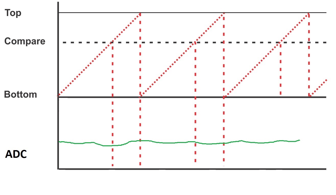
At the top side of the graphic I wanted to show system clock/timer signals. Let's say it is a 1ms timer/clock. The bottom graph shows my ADC feedback (SOC etc).
At timer's compare or overflow value, I want to start reading ADC fb values, I want to sum those feedback samples (integrator logic) maybe every 10us or 100us until timer's compare/overflow value ends.
Then according to that total ADC fb value I calculated, by comparing with a suitable value, I want to change my ePWMs' duty cycle at next pwm period. I want to do that "cycle by cycle".
I think LAUNCHXL-F28069M is fast enough to do this. Actually, way faster for what I need. But I want to be sure if it is possible.
Plus, could you tell me which reqisters I should use to detect system timer's overflow time range? Is there any spesific one?
Thanks for your attention.

