This thread has been locked.

If you have a related question, please click the "Ask a related question" button in the top right corner. The newly created question will be automatically linked to this question.

TMS320F28075: Question on connecting VssOSC and the board ground

Part Number: TMS320F28075
Other Parts Discussed in Thread: C2000WARE, UNIFLASH

We have recently designed a custom board with the piccolo F28075 as the MCU. My understanding from the datasheet is that the crystal oscillator ground pin (VssOSC) should not be connected to the board ground. However, our first prototype board would not program (using CCS and an XDS100v2) until we connected this pin to the board's ground plane. When trying to debug it using the XDS100 a popup would come up stating that the MCU was in a low power mode and asking whether to wake the board. After clicking the yes button, the connection would fail with a "No Power/Clock" message in the debug window.

We have also recently designed another board with the F28377D as the MCU. On this board we did not have any trouble programming the board.

I will need to revise the layout of the F29075 PCB. Please can someone advise on what the best practice is regarding connecting VssOSC and the board ground/the MCU ground.

Thanks

Alex

  • Hi Alex,

    What XTAL are you using here? Can you post the relevant snippets from your schematic and layout?

    (If you can't easily post these without also posting proprietary information, you can send an email referencing this thread with your files to c2kforum@list.ti.com)
  • Hi Devin, thank you for your reply. I apologize for replying to you so slowly. I thought I would get an email notification but didn't.

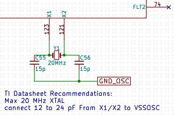
    The part number of the crystal i used is: Qantek - QCL20.0000F18B23B (RS - 814-9456).

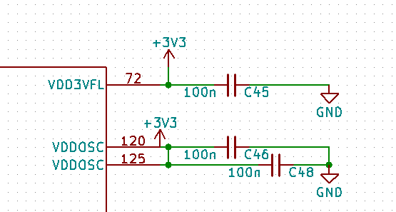
    The relevant parts of the schematic are shown below.

    As an update, I am now further along with testing all the peripherals and need to start programming the code to flash. However I am again encountering problems here. If i load the blinky example and use the CPU1_RAM build configuration the program loads successfully. However if I swap over to the CPU1_Flash configuration, the

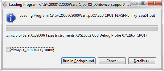
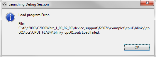
    The loading program popup first hangs as per the screenshot below and then eventually fails.

    Here's the output in the console

    C28xx_CPU1: GEL Output:
    Memory Map Initialization Complete
    C28xx_CPU1: Error: (Error -1044 @ 0x0) The debug probe reported an error. Confirm debug probe configuration and connections, reset the debug probe, and retry the operation. (Emulation package 7.0.48.0)
    C28xx_CPU1: Unable to determine target status after 20 attempts
    C28xx_CPU1: Failed to remove the debug state from the target before disconnecting. There may still be breakpoint op-codes embedded in program memory. It is recommended that you reset the emulator before you connect and reload your program before you continue debugging
    C28xx_CPU1: Error occurred during flash operation: Could not write 0x00000064@Data: target is not connected
    C28xx_CPU1: Error occurred during flash operation: Could not read 0x00130@Program: target is not connected
    C28xx_CPU1: Error executing PLL configuration algorithm. Operation cancelled. (0x0)
    C28xx_CPU1: File Loader: Memory write failed: Unknown error
    C28xx_CPU1: GEL: File: C:\ti\c2000\C2000Ware_1_00_02_00\device_support\f2807x\examples\cpu1\blinky\cpu01\ccs\CPU1_FLASH\blinky_cpu01.out: Load failed.
    C28xx_CPU1: Error occurred during flash operation: Could not read register PC: target is not connected
    C28xx_CPU1: Error occurred during flash operation: Could not write 0x0005F800@Data: target is not connected
    C28xx_CPU1: Error occurred during flash operation: Could not write 0x0005FC00@Data: target is not connected
    C28xx_CPU1: Error occurred during flash operation: Could not write 0x00000@Program: target is not connected
    C28xx_CPU1: Error occurred during flash operation: Cannot enable while the target is disconnected
    C28xx_CPU1: Error occurred during flash operation: Could not read 0x00000064@Data: target is not connected
    C28xx_CPU1: Error occurred during flash operation: Could not write 0x00000064@Data: target is not connected
    C28xx_CPU1: Error occurred during flash operation: Failed to run target while trying to execute pwrite_en.alg
    C28xx_CPU1: Flash operation timed out waiting for the algorithm to complete. Operation cancelled.
    C28xx_CPU1: Perform a debugger reset and execute the Boot-ROM code (click on the RESUME button in CCS debug window) before erasing/loading the Flash. If that does not help to perform a successful Flash erase/load, check the Reset cause (RESC) register, NMI shadow flag (NMISHDFLG) register and the Boot-ROM status register for further debug.
    C28xx_CPU1: Error occurred during flash operation: Could not write 0x00000064@Data: target is not connected
    C28xx_CPU1: Error occurred during flash operation: Could not read 0x0005D20E@Data: target is not connected
    C28xx_CPU1: Error occurred during flash operation: Could not write 0x0005D20E@Data: target is not connected
    C28xx_CPU1: Error occurred during flash operation: Could not read 0x0005D20E@Data: target is not connected
    C28xx_CPU1: Error occurred during flash operation: Could not write 0x0005D20E@Data: target is not connected
    C28xx_CPU1: Error occurred during flash operation: Could not read 0x0005D22E@Data: target is not connected
    C28xx_CPU1: Error occurred during flash operation: Could not read 0x0005D208@Data: target is not connected
    C28xx_CPU1: Error occurred during flash operation: Could not write 0x0005D208@Data: target is not connected
    C28xx_CPU1: Error occurred during flash operation: Could not read 0x0005D208@Data: target is not connected
    C28xx_CPU1: Error occurred during flash operation: Could not write 0x0005D208@Data: target is not connected
    C28xx_CPU1: Error occurred during flash operation: Could not read 0x0005D222@Data: target is not connected
    C28xx_CPU1: Error occurred during flash operation: Could not write 0x0005D222@Data: target is not connected
    C28xx_CPU1: Error occurred during flash operation: Could not write 0x0005D214@Data: target is not connected
    C28xx_CPU1: Error occurred during flash operation: Could not read 0x0005D20E@Data: target is not connected
    C28xx_CPU1: Error occurred during flash operation: Could not write 0x0005D20E@Data: target is not connected
    C28xx_CPU1: Error occurred during flash operation: Could not write 0x0005D20E@Data: target is not connected
    C28xx_CPU1: Error occurred during flash operation: Could not write 0x0005D222@Data: target is not connected
    C28xx_CPU1: Error occurred during flash operation: Could not write 0x00000@Program: target is not connected
    C28xx_CPU1: Error occurred during flash operation: Cannot enable while the target is disconnected
    C28xx_CPU1: Error occurred during flash operation: Could not read 0x00000064@Data: target is not connected
    C28xx_CPU1: Error occurred during flash operation: Could not write 0x00000064@Data: target is not connected
    C28xx_CPU1: Error occurred during flash operation: Failed to run target while trying to execute pwrite_dis.alg
    C28xx_CPU1: Flash operation timed out waiting for the algorithm to complete. Operation cancelled.
    C28xx_CPU1: Perform a debugger reset and execute the Boot-ROM code (click on the RESUME button in CCS debug window) before erasing/loading the Flash. If that does not help to perform a successful Flash erase/load, check the Reset cause (RESC) register, NMI shadow flag (NMISHDFLG) register and the Boot-ROM status register for further debug.
    C28xx_CPU1: Error occurred during flash operation: Could not write 0x00000064@Data: target is not connected
    C28xx_CPU1: Error occurred during flash operation: Could not write register PC: target is not connected

  • I am using CCS Version: 7.2.0.00013, and the example projects from C2000Ware_1_00_02_00.
    I have the boot pins setup for wait mode, i.e. GPIO72 high and GPIO84 low.
  • I have now tried UniFlash. I get the same error messages when I try to load the .out file.
    If I click the "verify image" button, I get the error message:
    "[ERROR] C28xx_CPU1: File Loader: Verification failed: Values at address 0x82001@Program do not match Please verify target memory and memory map."
  • Alexander,

    Did you notice a toggle on XRSn when the Flash load is initiated?
    Did you check if there is any dip in voltage lines during erase or program operation?

    Also try: Once you configure the boot mode pins to wait mode, do a power cycle before you load the code to Flash.

    Thanks and regards,
    Vamsi
  • Hi Vamsi,

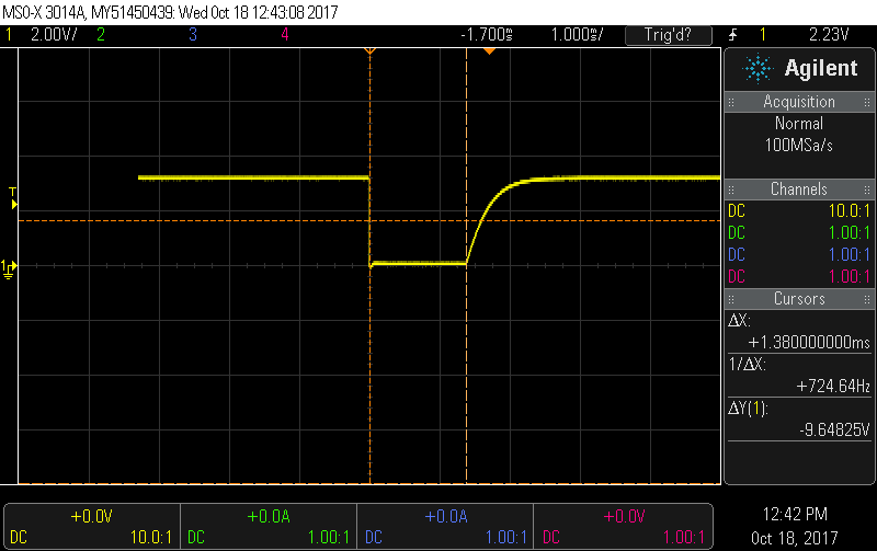
    There is a single toggle on the XRSn when trying to load the program. The pin goes low for ~1.4ms and then rises back up over ~0.5ms (see below). The power lines are stable at 3.3V.

  • Alexander,

    When the flash load fails, is the target still connected? If yes, can you check the value of RESC register (address 0x5D380), NMISHDFLG register (address 0x7066) and 32-bit value at address 0x0000002C in the CCS memory window?

    Thanks and regards,
    Vamsi
  • The target is disconnected. Tho fourth message in the long list of errors that appear in the console is:

    "C28xx_CPU1: Error occurred during flash operation: Could not write 0x00000064@Data: target is not connected"

    Tomorrow I will look again at the 3v3 supply to VDD3VFL (pin 72). Before I just monitored the output of the 3v3 regulator.

  • 3v3 supply to VDD3VFL (pin 72) is constant at 3.3V
  • We isolated the external 1.2V voltage regulator, and enabled the internal 1.2V reg by tying /VREGEN low.
    This has solved the problem of programming the flash.
  • Alexander,

    Glad to know that the issue is fixed.

    Thanks and regards,
    Vamsi