This thread has been locked.

If you have a related question, please click the "Ask a related question" button in the top right corner. The newly created question will be automatically linked to this question.

LAUNCHXL-F28379D: TIDM-DELFINO-ETHERCAT configuration, TwinCAT 3.

Part Number: LAUNCHXL-F28379D
Other Parts Discussed in Thread: TIDM-DELFINO-ETHERCAT, CONTROLSUITE, TMS320F28379D, TMDSECATCNCD379D, TMDSCNCD28379D

Hello everyone :)

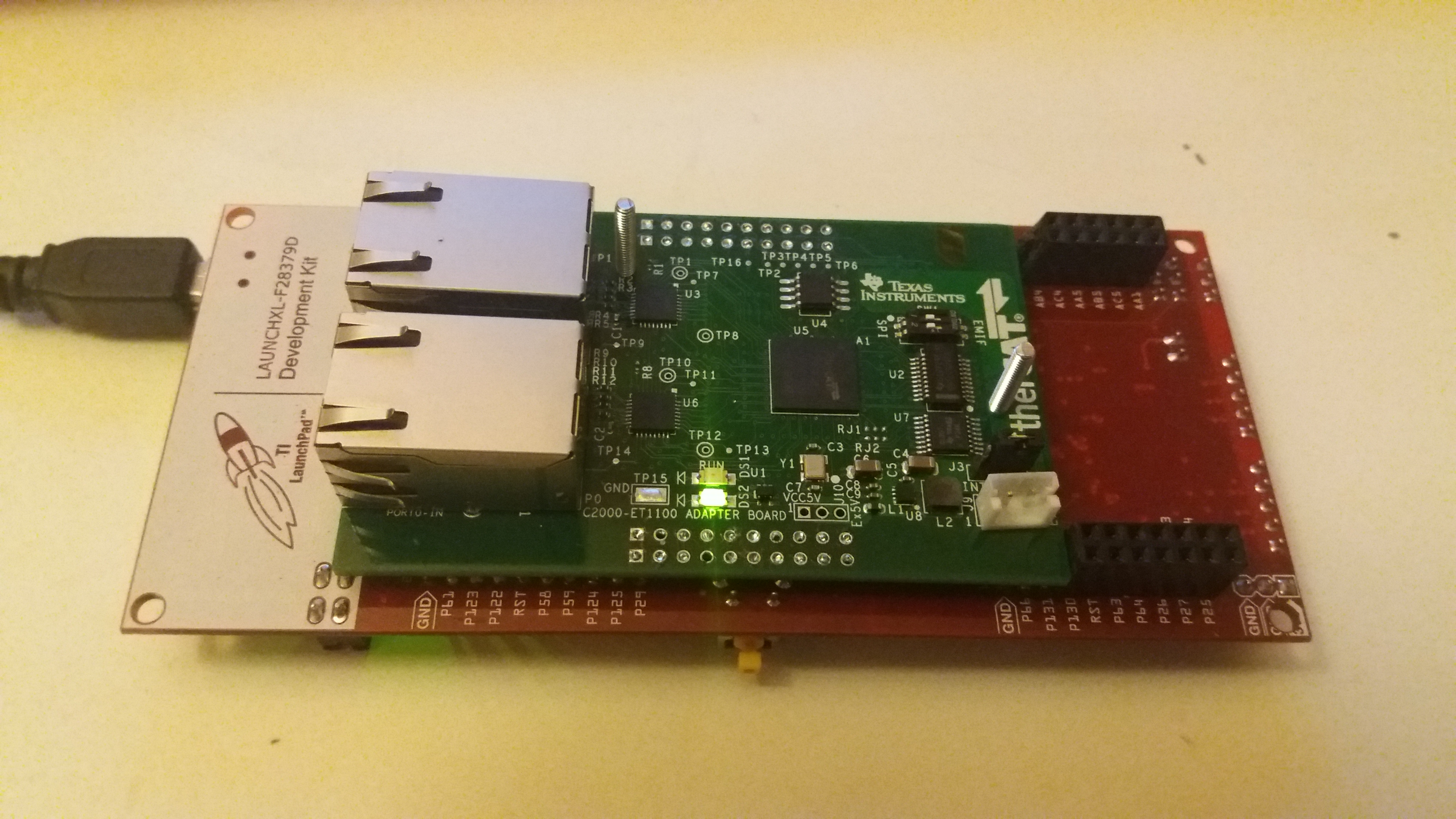
It's my pleasure to be here and this is my first post. Well, I have a problem. I have this launchpad: www.ti.com/tool/LAUNCHXL-F28379D and these etherCAT modules: www.ti.com/tool/TIDM-DELFINO-ETHERCAT

 I was doing step-by-step from that document: www.ti.com/lit/ug/tidubq6a/tidubq6a.pdf 

empty.

After launch TwinCAT XAE (VS 2015) and scan for new devices I accept "Scan for boxes" and "Activate free run" messages and after that I can see that my etherCAT device was found BUT Visual Studio shows me errors, code (1001) and timeouts.

My ethernet card is from Intel and it's in "Installed and ready to use devices (realtime capable)" section.

I have completely no idea what I have to do to run EtherCAT on those modules. Did anyone of You launch it? Do you have any ideas what I should do to launch it?

Thank you for your answers,

David.

  • Something cut some of my post.

     I was doing step-by-step from that document: www.ti.com/lit/ug/tidubq6a/tidubq6a.pdf  but it didn't work like in document. I set jumpers just like in document.

    And after I've wrote pdi_test_app_spi.bin to an EEPROM my smart view looked like that: 

    In Device Identity I have different numbers: Serial No. is 0x0000000, Revision No. is different too. Furthermore, Mailbox section is COMPLETETLY empty - CoE checkbox isn't checked, Bootstrap Configuration and Standard Configuration are empty.

  • Dawid,
    the SW provided with TI Design doesn't have EtherCAT stack support.

    Please see if you can start with www.ti.com/.../tmdsecatcncd379d . The SW for this kit is provided in controlSuite.


    Best Regards
    Santosh Athuru
  • Could you explain what is SW?
    And please, tell me if I am wrong - EtherCAT stack support should be implemented in TMS320F28379D, right?
    One more thing - I have ControlSuite installed but when I am typing TMDSECATCNCD379D nothing is showing up. Where I should looking for SW for TMDSECATCNCD379D?
  • Do you know if slave stack code can be found on open source version?
  • Dawid,

    Please follow the documentation provided, the SW (SoftWare) should be available in controlSuite folders as below.
    \controlSUITE\development_kits\TMDSECATCND379D_V1.0

    There are two PDFs provided, one is in HW and getting started with Demo guide (SPRUIF9) and other is Solution reference guide (SPRUIG9).

    Please check ETG website for information on EtherCAT Slave stack, users can get the Slave Stack Code after becoming an ETG member and downloading the SSC (Slave Stack Code) tool from ETG website.

    Best Regards
    Santosh Athuru
  • I found it, but you didn't say that TMDSECATCND379D_V1.0 is in the latest version odf ControlSUITE :)
    Tell me if I am wrong - stack source code is necessary to prepare a bin file to load it to an EEPROM? The stack control is in this file, right?
  • We have provided demo files (OUT Files or binary) that user can program onto the kit and evaluate an EtherCAT slave node on the kit. To get kit recognized from master and to program the EEPROM, the needed ESI files are also provided.

    Now once the user gets past understanding the demo and how to talk to the slave node from a master, user can get to the solution reference project and slave stack sources as explained in the documents.

    From your question it looks like you will have to first understand the EtherCAT slave, there are good documents and help on the ETG website. Our documents should provide the reference links to the ETG/Beckhoff documents that will help you the basics of the EtherCAT slave.

    Best Regards
    Santosh Athuru
  • I read documents you said. There were very helpful and I am studying them all the time.

    I found out that to download Slave Stack Code I need to become ETG member and get vendor ID. And my school is in progress with that.

    I really need to run demo which TI provided because I have to show it in school.  As I read in spruif9.pdf, point 4.2 EchoBack Demo, I can use *.xml to program an EEPROM and .out files with precompiled app for TMS320F28379D. And I programmed EEPROM with .xml supports SPI and programmed flash with TMDSECATCNCD379D_EchoBack_Demo_SPI_FLASH. But I still cannot establish a proper connection. As I suppose, TwinCAT see a node properly, but nothing else is happening. Please, look at the screen. Do you know how can I establish connection properly?

  • Dawid,

    no worries, you are close. Getting started with demo is good first step, please follow below steps. From your snapshot and explanation it looks like you already did some of the steps, I still list them below in brief to help cross verify.

    1.> The TMDSECATCNCD379D supports EMIF (or ASYNC16) and SPI modes. There is a switch on the board (ref. to documentation) which lets you select this. First step is to choose which PDI mode you want to use. We have demos and SW collateral support for both modes.

    Lets say you choose EMIF.

    2.> Now in the Demo folder (...\development_kits\TMDSECATCND379D_V1.0\TMDSECATCNCD379D_EchoBack_Demo) you will see below files.

    *.xml ==== These are the ESI files. You will have to copy these files to TwinCAT\3.1\Config\Io\EtherCAT folder, so that the master will know about the slave nodes. 

    *.out ==== These are the pre-compiled binaries that you will need to program on the kit using JTAG. You will have to use CCS (code composer Studio) and JTAG to connect to the target board (just like for any other controlSuite examples), the steps are documented in the user guides that come with the kit as well. 

    Once you connect CCS to the target you will have to use the load program option and select the pre-compiled binary and you will choose the *_SPI_FLASH*.out if you have chosen SPI PDI in step 1 or you will choose the *_ASYNC16_FLASH*.out file if you choose EMIF option.

    Once the board is programmed with the demo binary, proceed to step 3. Step 2 is much simpler than it looks if you have some prior experience with TI control cards or Launchpads.

    3.> Now connect the Port 0 of the TMDSECATCCND379D to the laptop/PC running TWINCAT. 

    From your snapshot I already assume you know how to use TWINCAT.

    4.> Scan for the nodes on the EtherCAT network and select the node. Now you will have to program the EEPROM with proper binary image and the ESI files you copied in step 2 will help now. (you might have to restart TWINCAT or have it reload the device ESI descriptions if you copied the ESI (XML) files while TWINCAT was already open. 

    Now again you will have to select the proper ESI file, if you chose SPI in step 1 then choose the *(SPI).XML or if you chose EMIF then use *(ASYNC16).XML.

    This is section 8 of www.ti.com/.../spruig9.pdf

    5.> Rescan the network and you should see the node correctly and it should go to 'op' mode if you refresh and the slave node should go to OP Mode. 

    6.> if the slave node is not in OP Mode then try to manually set the slave to OP mode from TwinCAT. If the slave is not in OP Mode the outputs will not set. You can also tell if the slave node is in OP mode or not by looking at the RUN LED on the board.

    7.> once the slave node is in OP mode, set the outputs. For ex: if you set the LEDs, the Switches will be set . All the ouputs are reflected back in inputs as per table 6 in ttp://www.ti.com/lit/ug/spruig9/spruig9.pdf

    let me know if it works.

    Best Regards

    Santosh Athuru

  • I followed the steps exactly like you described. And my etherCAT node still is not in OP mode, even after manually request. Here is screen with an error:

    Do you have any idea why it is happening?

  • I can add, that green led on RJ45 is blinking and orange led on RJ45 is lighting still.
  • Dawid,
    can you check and let me know on below:-

    1.> did you connect the Ethernet cable to PORT IN on the kit?

    2.> do you see the power LEDs on the controlCard and the EtherCAT board (GREEN LEDs)?

    3.> How are you powering up the board?

    4.> what is the name of the Binary file you programmed on the KIT using CCS?

    5.> waht is the name of the ESI file you chose to program the EEPROM? Can you send a snapshot of the EEPROM contents as read from the EtherCAT master?

    6.> What is the SW1 switch position on the kit point to?


    Best Regards
    Santosh Athuru
  • I am using Lauchpadxl-F28379D instead ControlCard, but I cut plastic bars and I could link etherCAT board to the J9 socket in Launchpad. I need to use J9 socket because there is SPI-C and EMIF.

    Ad. 1. Of course.

    Ad. 2. Yes I do.

    Ad. 3. I am powering the board from Launchpad.

    Ad. 4. TMDSECATCNCD379D_EchoBack_Demo_SPI_FLASH.out

    Ad. 5. TMDSECATCNCD379D EtherCAT slave (SPI).xml

    Ad. 6. SW1 is on the left, in SPI position.

    Here is photo of my board:

    Here is snapshot from EEPROM reading:

  • ah, now I understand your board , thanks for the PIC. So you are using LaunchPAD, can you tell me the version of the LaunchPAD XL you are using?
    what other versions of LAUNCHPAD XL you have on hand?

    Also your pic doesn't show Ethernet cable connected to PORT-IN, I assume you took it out for the pic.

    Best regards
    Santosh Athuru
  • Sure, I took it in just after taking the pic.

    My board is C2000 LaunchPad XL TMS320F28379D ver. 1.1

    Here is the photo:

  • with version 1.1, you will have to cross check the signals used between LaunchPAD XL and the EtherCAT daughter card.

    The demo binaries only work for the TMDSECATCCNCD379D kit, the SPI and PDI port (J9) signals that get routed onto control cards J9 and the LAUNCH PAD J9 are different.

    You will have to go through the Solution reference example route (www.ti.com/.../spruig9.pdf) and redefine the signals used in the etherCAT_slave_c28x_hal.h file and rebuild the binary.

    Until you get the ETG membership, you can start looking at the PDI HAL API test App (C:\ti\controlSUITE\development_kits\TMDSECATCND379D_V1.0\TMDSECATCNCD379D_PDI_HAL_API), modify the HAL header file for your board connections and check the PDI port operation.


    Hope this helps.

    Best Regards
    Santosh Athuru
  • I checked signal on Launchpad and Control Card. They match:

    And this is something I don't understand. How the PDI HAL API test App will help me when I haven't get the stack source code? Will I establish connection properly between boards and TwinCAT using that app?

  • No, by control card I mean this one www.ti.com/.../tmdscncd28379d. The TMDSECATCCND379D kit uses this control card, if you have one available you can probably use it instead of the launch pad. The schematic for control card can be found in controlSuite (C:\ti\controlSUITE\development_kits\~controlCARDs\TMDSCNCD28379D_v1_0\R1_3), page 3 shows J9 connections from the MCU.

    The SW provided with the TMDSECATCCND379D kit uses these signals.

    The launch pad J9 is one what you have put above, but we have a v2.0 launch pad available now. You should be fine with this one for now, but you will have to check for changes when you move to v2.0


    The PDI HAL API Test just helps user verify the PDI connections by reading/writing to the ESC RAM. It doesn't need a stack, and is mainly provided for users who want to verify the HW before getting into stack and applications.

    Best Regards
    Santosh
  • Get it. using demo app I can just read registers from ET1100, right?

    But I hve another question. In ET1100 datasheet I read this:


    6.3.10 EEPROM_LOADED
    The EEPROM_LOADED signal indicates that the SPI Interface is operational. Attach a pull-down
    resistor for proper function, since the PDI pin will not be driven until the EEPROM is loaded.

    So I set GPIO52 on the Launchpad as an input and I realized that after program an EEPROM with SPI mode this pin is still logical 0, I checked it in Expressions window. I suppose this pin should be high after program an EEPROM, right?

  • EEPROM loaded will be set high by the ESC after the EEPROM contents are ready by the ESC on reset. If the EEPROM loaded signal is not going high, please check if there is any CRC error with the first 15 bytes of the EEPROM contents and also you can try resetting the ESC and see if the EEPROM load gets re-triggered.

    Best Regards
    Santosh Athuru
  • Dawid,
    can you let us know if the issues are closed and you have made progress with your solution?

    can this thread be closed?

    Best Regards
    Santosh Athuru
  • Hi,

    I fortunately run demo app and ESC's memory is read correctly. I has to add DC_LP in predefined symbols and use ***. And ecerything works fine, EEPROM_LOAD signal is present.

    Thank you for your help. This thread can be closed :)

  • Hi Dawid,

    thanks for posting your solution. Glad you are able to get your LaunchPAD setup working. 

    Best Regards

    Santosh Athuru