This thread has been locked.

If you have a related question, please click the "Ask a related question" button in the top right corner. The newly created question will be automatically linked to this question.

CCS/TMDSSOLARPEXPKIT: TMDSSOLARPEXPKIT, Solar Explorer Kit, How to get it connected and running?

Part Number: TMDSSOLARPEXPKIT

Tool/software: Code Composer Studio

Hello, everyone

This is my first time trying to use something like this, TMDSSOLARPEXPKIT, Piccolo based Solar Explorer Kit. I found myself having some difficulties trying to connect it to PC.

I have a Win 10 64 bit system, all I am trying to do now is to have a general idea of how this board is operated and how to modify it. First I need to run some built in functions.

All the documents I have are

1),Hardware and Control Reference Guide;

2), Using GUI Composer: Step-by-Step Guide;

3), C2000 Microcontrollers Development Tools User Guide;

Software wise, I have installed

1), Control Suite

2), Code Composer Studio 6.2.0 (Tried to install 5.5.0, but could not build project in this version)

3), Guicomposer

Below are some specific questions.

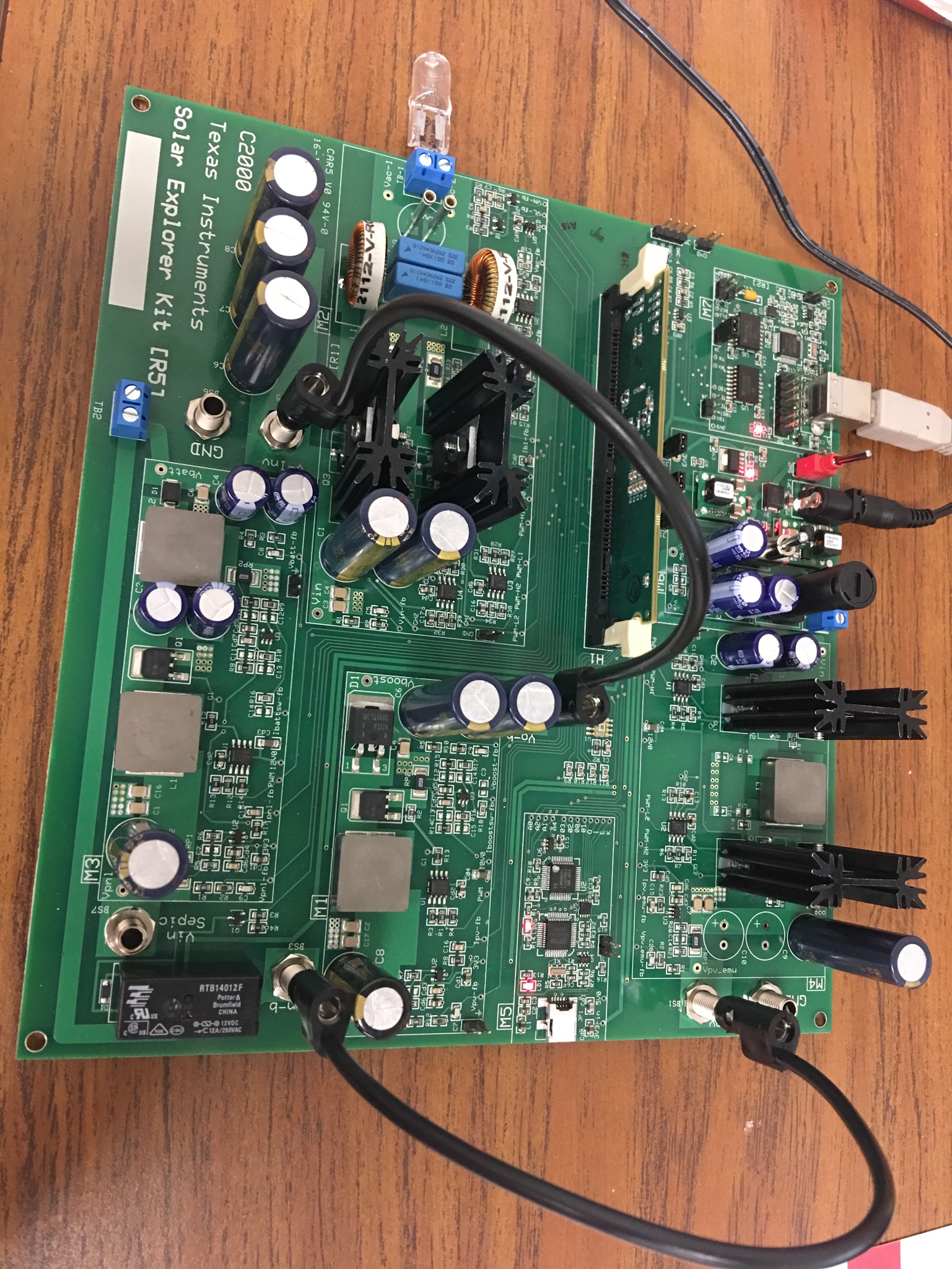
  • About hardware connection. First, the power input is 20VDC, 2A, so 40W in total. However the PV Emulator is 50W, how can a 40W power source support a 50W emulator? Second, As shown below, with the only two banana canles, I have connected BS1 and BS3, BS4 and BS5. From the PV emulator to inverter, it should be all linked by now. Then can I assume that I have done the hardware interconnection on the board? If so, How can I link all the parts of the system together? Because with all I have, I cannot connect all BS1, BS7 and BS3 three together.

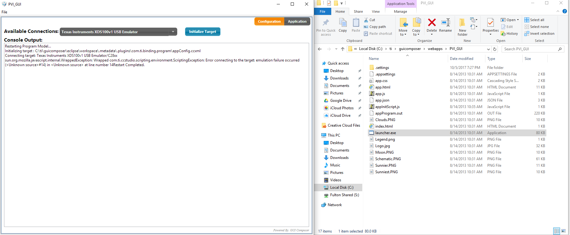
  • About GUI Connection. From what I understand, GUI is a demonstration-friendly app-like program. I tried to run the given demo Gui with board connected via USB while powered on, but got stuck at initialization phase. I have followed the instructions in  "GUI Connection" step by step (4 steps in total), but it doesn't work.
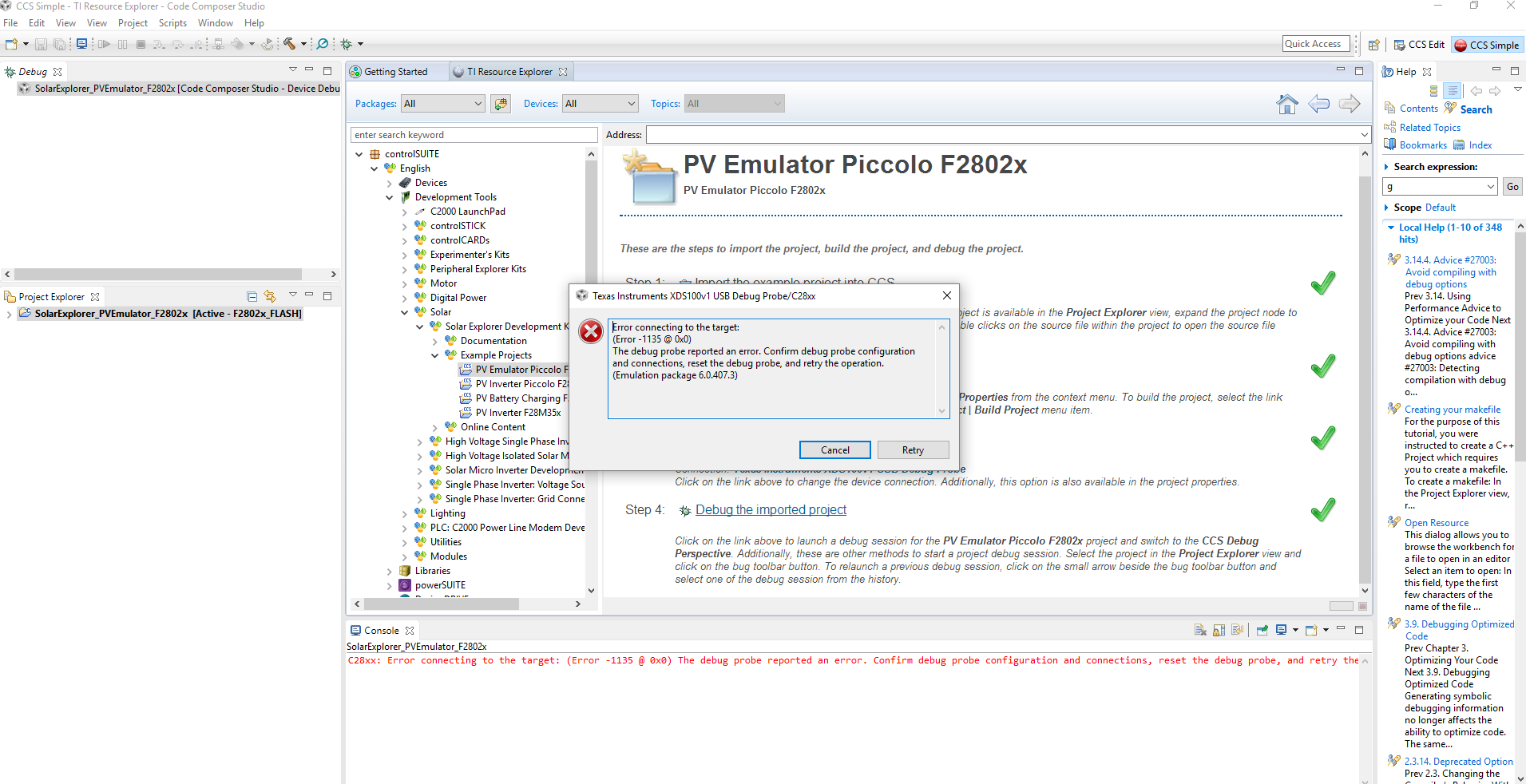
  • About CCS. From what I understand, the board has built-in control functions, do not need CCS to copy the given project. However, when I try to run the given project through given steps, I have problem in step 4. Screenshots are shown below. This problem also happened with other projects.
Thanks!

Best regards

Yue

    • About hardware connection. First, the power input is 20VDC, 2A, so 40W in total. However the PV Emulator is 50W, how can a 40W power source support a 50W emulator?50W is the max power, the programmed emulator is max ~40W , please see the UG. Hence a 2 Amps supply is sufficient. If you wish to connect a 2.5Amps supply you can. 
    • Second, As shown below, with the only two banana canles, I have connected BS1 and BS3, BS4 and BS5. From the PV emulator to inverter, it should be all linked by now. Then can I assume that I have done the hardware interconnection on the board? If so, How can I link all the parts of the system together? Because with all I have, I cannot connect all BS1, BS7 and BS3 three together. The number of cables needed will depend on the system you are trying to build or test. We provide 2, for the PV inverter system. This is what is listed in what's included. You can use additional if you want to test some other system. They are easy to procure and are typically available in lab's etc. The battery charging system that will need the third cable was added after we released the EVM.  
    • About GUI Connection. From what I understand, GUI is a demonstration-friendly app-like program. I tried to run the given demo Gui with board connected via USB while powered on, but got stuck at initialization phase. I have followed the instructions in  "GUI Connection" step by step (4 steps in total), but it doesn't work. You need to populate the jumper [Main] J4
    • About CCS. From what I understand, the board has built-in control functions, do not need CCS to copy the given project. However, when I try to run the given project through given steps, I have problem in step 4. Screenshots are shown below. This problem also happened with other projects. I think [Main]-J4 will be the culprit here too...  

  • Thanks for your reply, actually I have just completed populating Main-J4, as shown below.

    For now the light of the controller card is with only the power indicator on, the output of Panel Emulator is 0V (5.5V with Main-J4 unpopulated) and CCS is showing the following message:

    From the hardware guide, Main-J4 enables JTAG connection to controller, I assume with Main-J4 populated, it enters the connection mode and thus no output will be given in this mode. However I still cannot load the project with this configuration. I have tried delete them and restart it all over again still not working.

    Thank you.

    Best regards,

    Yue

  • By the way, since the main controller, F28035, and the controller used for PV emulator, F28027, used different port. One use Ethernet while the other use Mini-USB. I have plugged them both into my PC. I wonder if they are use both XDS100-V1 USB Debug Probe setting. If yes, how the PC knows which one it's talking to when both controllers are connected? Thank you.
  • Hello Manish,

    Today I solved the debug Step 4 problem, I used the jumper in the opposite position and caused failure. However I still cannot use GUI program that came with the board. you said "[main]J4 should be populated", but in "GUI Connection"  in Hardware Reference Guide, it told me to populate [M7] J4 and remove the [Main] J4, which is opposite from what you told me. I have tried both, by doing what you told me it really did something and gave me info like this:

    While doing what Reference told me still gave me info like what Ive posted before. I wonder what did reference meant.

    For now:

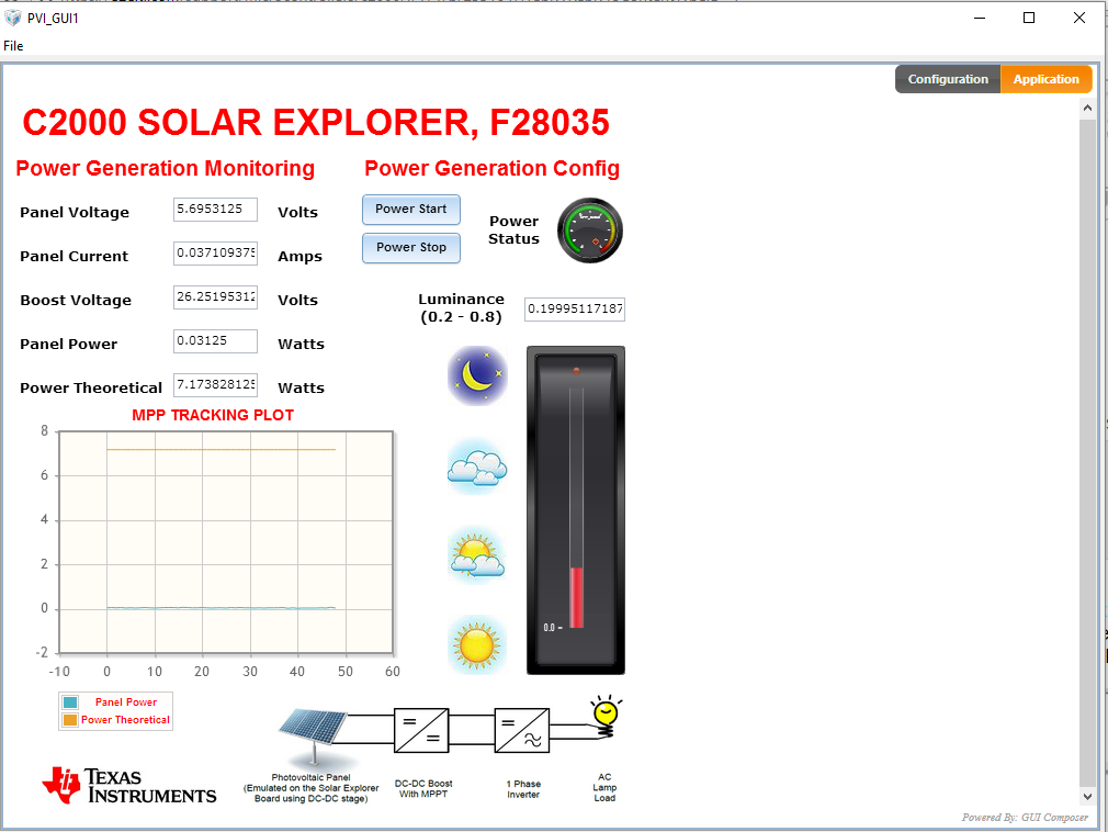
    • I am not sure if I am getting the MPP from the MPP Tracking Plot, cause it's continued to be two parallel lines... 
    • Another thing is the AC side gave me nothing (no voltage and 50W led is not lit), how do I manage to get the inverter working? In "e2e.ti.com/.../583882 , I found that someone suggested flashing the code again, ("Try flashing the code again. Here's the code location: 
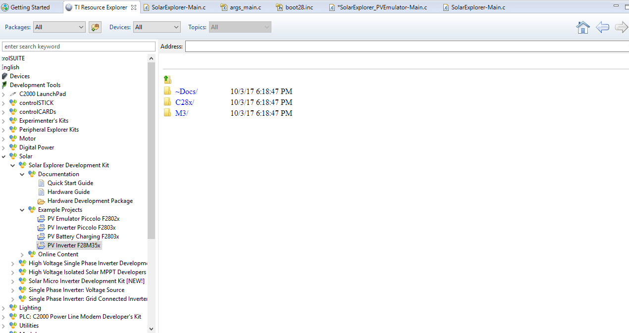
      C:\ti\controlSUITE\development_kits\SolarExplorer_v1.1") but how am I supposed to do that? Does that means reloading the 3 given projects (3 instead of 4 because the 4th project gave me info shown below )with given 4 steps?

    Sorry for raising so much questions, and some of which are solved without answer given so I would assume those are pretty silly ones. But I think this could be a good reference for someone like me with little background in the future has similar problems. Thank you.