Because of the holidays, TI E2E™ design support forum responses will be delayed from Dec. 25 through Jan. 2. Thank you for your patience.

This thread has been locked.

If you have a related question, please click the "Ask a related question" button in the top right corner. The newly created question will be automatically linked to this question.

TMS320F28377S: TMS320F28379D: USB examples from C2000Ware events problems

Part Number: TMS320F28377S
Other Parts Discussed in Thread: C2000WARE

Hello,

This is about the problem related in the following post but the discutions was locked! (why ???)

e2e.ti.com/.../2184780

The problem was about the USB device disconnect event which is never received.

The problem was transmitted to an engineer, but we don't have any news today.

The C2000ware v01.00.02.00 is available since some day.

If somebody can say me if this version correct this problem?

If no, is somebody can work on it? Because we are in production phase now, and this problem is very blocant for us.

Thank

Regards

  • This has not been fixed in the latest C2000Ware release yet.

    sal

  • We should be looking at this issue and the USBlib and USB examples towards the end of October.
  • Hello

    Still no news about the resolution of this problem?
    Thank
  • Hello

    No reply from this post?
    Regards,
  • Hi,

    I have re-run the usb_dev_serial example and am seeing no issues. The device can connect, disconnect and re-connect with no problem.

    Regards,
    sal
  • Hello,

    I re-run the following example:
    C:\ti\c2000\C2000Ware_1_00_03_00\device_support\f2837xd\examples\cpu1\usb_dev_serial
    I compile it on CCS v7.4
    A warning appears:
    "This project was created using a version of compiler that is not currently installed - 15.12.1.LTS [C2000]. Another version of the compiler will be used during build - 16.9.6.LTS."

    I run it on controlCard F28377D rev 1.1. (With onchip XDS100v2)

    I get the Connected event when USB cable is plugged, but no event when USB cable is unplug. (g_pcStatus is set to "Connected" when cable is plugged and stay at this state when cable is unplug instead of pass to "Disconnected")


    Then in project properties, I Changed the Compiler version to TI v16.9.6.LTS=> Same result
    Then in project properties, I Changed the Compiler version to TI v17.9.0.STS=> Same result

    Then this no wok from my side.

    What was your environment to test the exemple? (board, version etc....)
    Which think could read in debug mode to find where come from the problem?

    Thank for your back. This is important for us and can compromise our project.
  • Hi,

    I was using the latest F2837xD (F28379D) rev 1.3 controlCARD with rev C silicon. There have been some USB related changes to the controlCARD schematic since rev 1.1.

    You can see the changes detailed in this document: F2837x_180controlCARD_R1_3_SCH_02Oct2015 under the /boards folder in C2000Ware.

    The changes have to do with properly disconnecting the device from the host. We have added a couple resistors to properly drain the voltage on VBUS. Please see the schematic for more details.

    Hope this helps.

    sal
  • Hello

    Ok,
    After the controlCard, we develop our own specific board on which the connect/disconnect detection not work also.

    I bad understand on the Rev 1.3 which part is just necessary to have this function?
    On My specific board, we have simplify the schematic like following:

    - µC signal USB0DM linked to USB connector D- (pin 2)
    - µC signal USB0DP linked to USB connector D+ (pin 3)
    - USB connector GND Pin 5 linked to the board GND.

    - TPD2E2 : ESD clamp on D+ and D- signal


    And that all!

    Which is the minimum request that I must add to do the USBLib detect the connect/disconnect ?

    Thank

  • Please see page 6 for the USB schematic on the controlCARD.

    Also, you can use another GPIO pin, for example GPIO 46, to detect connection and disconnection.

    In your main application you can use the below code.

       //

       // check if VBUS is high or low at start up because this would not cause an interrupt.

       //

    if(GpioDataRegs.GPBDAT.bit.GPIO46 == 1)

    {

    USBDevConnect(USB0_BASE);

    }

    else

    {

    USBDevDisconnect(USB0_BASE);

    }

    And set up an external interrupt to detect when VBUS goes high or low.

    //

    // VBUS interrupt.
    //
    EALLOW;
    PieVectTable.XINT1_INT = &vbus_isr;
    EDIS;
    //
    // Enable XINT1 in the PIE: Group 1 interrupt 4
    //
    PieCtrlRegs.PIECTRL.bit.ENPIE = 1; // Enable the PIE block
    PieCtrlRegs.PIEIER1.bit.INTx4 = 1; // Enable PIE Group 1 INT4
    IER |= M_INT1; // Enable CPU INT1
    //EINT; // Enable Global Interrupts

    //
    //setup GPIO46 for XINT1.
    //
    GPIO_SetupXINT1Gpio(46);
    //
    //Configure polarity for XINT1.
    //
    XintRegs.XINT1CR.bit.POLARITY = 3; //positive or negative edge trigger
    //
    //Enable XINT1
    //
    XintRegs.XINT1CR.bit.ENABLE = 1; // Enable XINT1

    //
    // Enable global interrupts
    //
    IntMasterEnable();

    And use the below ISR.

    //

    // on VBUS toggle connect or disconnect PHY.

    //

    __interrupt void vbus_isr(void)

    {

    if(GpioDataRegs.GPBDAT.bit.GPIO46 == 1)

    {

    USBDevConnect(USB0_BASE);

    }

    else

    {

    USBDevDisconnect(USB0_BASE);

    }

    PieCtrlRegs.PIEACK.all = 0xFFFF;

    }

    Additionally, you can see the attached USB main source code which we used to certify our controlCARD rev 1.3 for USB certification.

    sal

    usb_dev_bulk.c
    //###########################################################################
    // FILE:   usb_dev_bulk.c
    // TITLE:  Main routines for the generic bulk device example.
    //###########################################################################
    // $TI Release: F2837xD Support Library v180 $
    // $Release Date: Fri Nov  6 16:19:46 CST 2015 $
    // $Copyright: Copyright (C) 2013-2015 Texas Instruments Incorporated -
    //             http://www.ti.com/ ALL RIGHTS RESERVED $
    //###########################################################################
    
    //
    // This is used for USB certification. Device Mode.
    //
    
    #include "F28x_Project.h"
    #include <stdbool.h>
    #include <stdint.h>
    #include "inc/hw_ints.h"
    #include "inc/hw_memmap.h"
    #include "inc/hw_types.h"
    #include "driverlib/debug.h"
    #include "driverlib/interrupt.h"
    #include "driverlib/sysctl.h"
    #include "driverlib/systick.h"
    #include "driverlib/uart.h"
    #include "driverlib/usb.h"
    #include "driverlib/usb_hal.h"
    #include "driverlib/rom.h"
    #include "usblib/usblib.h"
    #include "usblib/usb-ids.h"
    #include "usblib/device/usbdevice.h"
    #include "usblib/device/usbdbulk.h"
    #include "utils/uartstdio.h"
    #include "usb_bulk_structs.h"
    
    uint16_t g_connected = 0; //hack for certification
    __interrupt void vbus_isr(void);
    
    //*****************************************************************************
    //! \addtogroup cpu01_example_list
    //! <h1>USB Generic Bulk Device (usb_dev_bulk)</h1>
    //!
    //! This example provides a generic USB device offering simple bulk data
    //! transfer to and from the host.  The device uses a vendor-specific class ID
    //! and supports a single bulk IN endpoint and a single bulk OUT endpoint.
    //! Data received from the host is assumed to be ASCII text and it is
    //! echoed back with the case of all alphabetic characters swapped.
    //!
    //! UART0, connected to the FTDI virtual COM port and running at 115,200,
    //! 8-N-1, is used to display messages from this application.
    //!
    //! A Windows INF file for the device is provided in ControlSUITE.  This
    //! INF contains information required to install the WinUSB subsystem on
    //! WindowsXP and Windows 7.  WinUSB is a Windows subsystem allowing user mode
    //! applications to access the USB device without the need for a
    //! vendor-specific kernel mode driver.
    //!
    //! A sample Windows command-line application, usb_bulk_example, illustrating
    //! how to connect to and communicate with the bulk device is also provided.
    //! Project files are included to allow the examples to be built using Microsoft
    //! VisualStudio.  Source code for this application can be found in directory
    //! F2837xD_common/tools/usb_bulk_example/Release.
    //*****************************************************************************
    
    //*****************************************************************************
    //
    // The system tick rate expressed both as ticks per second and a millisecond
    // period.
    //
    //*****************************************************************************
    #define SYSTICKS_PER_SECOND     100
    #define SYSTICK_PERIOD_MS       (1000 / SYSTICKS_PER_SECOND)
    
    //*****************************************************************************
    //
    // The global system tick counter.
    //
    //*****************************************************************************
    volatile uint32_t g_ui32SysTickCount = 0;
    
    //*****************************************************************************
    //
    // Variables tracking transmit and receive counts.
    //
    //*****************************************************************************
    volatile uint32_t g_ui32TxCount = 0;
    volatile uint32_t g_ui32RxCount = 0;
    #ifdef DEBUG
    uint32_t g_ui32UARTRxErrors = 0;
    #endif
    
    //*****************************************************************************
    //
    // The current USB operating mode - Host, Device or unknown.
    //
    //*****************************************************************************
    tUSBMode g_eCurrentUSBMode;
    
    //*****************************************************************************
    //
    // Debug-related definitions and declarations.
    //
    // Debug output is available via UART0 if DEBUG is defined during build.
    //
    //*****************************************************************************
    #ifdef DEBUG
    //*****************************************************************************
    //
    // Map all debug print calls to UARTprintf in debug builds.
    //
    //*****************************************************************************
    #define DEBUG_PRINT UARTprintf
    
    #else
    
    //*****************************************************************************
    //
    // Compile out all debug print calls in release builds.
    //
    //*****************************************************************************
    #define DEBUG_PRINT while(0) ((int32_t (*)(char *, ...))0)
    #endif
    
    //*****************************************************************************
    //
    // Flags used to pass commands from interrupt context to the main loop.
    //
    //*****************************************************************************
    #define COMMAND_PACKET_RECEIVED 0x00000001
    #define COMMAND_STATUS_UPDATE   0x00000002
    
    volatile uint32_t g_ui32Flags = 0;
    char *g_pcStatus;
    
    //*****************************************************************************
    //
    // Global flag indicating that a USB configuration has been set.
    //
    //*****************************************************************************
    static volatile bool g_bUSBConfigured = false;
    
    //*****************************************************************************
    //
    // The error routine that is called if the driver library encounters an error.
    //
    //*****************************************************************************
    #ifdef DEBUG
    void
    __error__(char *pcFilename, uint32_t ui32Line)
    {
        UARTprintf("Error at line %d of %s\n", ui32Line, pcFilename);
        while(1)
        {
        }
    }
    
    #endif
    
    //*****************************************************************************
    //
    // Interrupt handler for the system tick counter.
    //
    //*****************************************************************************
    __interrupt void
    SysTickIntHandler(void)
    {
        //
        // Update our system tick counter.
        //
        g_ui32SysTickCount++;
        PieCtrlRegs.PIEACK.all |= 1;
    }
    
    //*****************************************************************************
    //
    // Receive new data and echo it back to the host.
    //
    // \param psDevice points to the instance data for the device whose data is to
    // be processed.
    // \param pi8Data points to the newly received data in the USB receive buffer.
    // \param ui32NumBytes is the number of bytes of data available to be processed.
    //
    // This function is called whenever we receive a notification that data is
    // available from the host. We read the data, byte-by-byte and swap the case
    // of any alphabetical characters found then write it back out to be
    // transmitted back to the host.
    //
    // \return Returns the number of bytes of data processed.
    //
    //*****************************************************************************
    static uint32_t
    EchoNewDataToHost(tUSBDBulkDevice *psDevice, uint8_t *pi8Data,
                      uint_fast32_t ui32NumBytes)
    {
        uint_fast32_t ui32Loop, ui32Space, ui32Count;
        uint_fast32_t ui32ReadIndex;
        uint_fast32_t ui32WriteIndex;
        tUSBRingBufObject sTxRing;
    
        //
        // Get the current buffer information to allow us to write directly to
        // the transmit buffer (we already have enough information from the
        // parameters to access the receive buffer directly).
        //
        USBBufferInfoGet(&g_sTxBuffer, &sTxRing);
    
        //
        // How much space is there in the transmit buffer?
        //
        ui32Space = USBBufferSpaceAvailable(&g_sTxBuffer);
    
        //
        // How many characters can we process this time round?
        //
        ui32Loop = (ui32Space < ui32NumBytes) ? ui32Space : ui32NumBytes;
        ui32Count = ui32Loop;
    
        //
        // Update our receive counter.
        //
        g_ui32RxCount += ui32NumBytes;
    
        //
        // Dump a debug message.
        //
        DEBUG_PRINT("Received %d bytes\n", ui32NumBytes);
    
        //
        // Set up to process the characters by directly accessing the USB buffers.
        //
        ui32ReadIndex = (uint32_t)(pi8Data - g_pui8USBRxBuffer);
        ui32WriteIndex = sTxRing.ui32WriteIndex;
    
        while(ui32Loop)
        {
            //
            // Copy from the receive buffer to the transmit buffer converting
            // character case on the way.
            //
    
            //
            // Is this a lower case character?
            //
            if((g_pui8USBRxBuffer[ui32ReadIndex] >= 'a') &&
               (g_pui8USBRxBuffer[ui32ReadIndex] <= 'z'))
            {
                //
                // Convert to upper case and write to the transmit buffer.
                //
                g_pui8USBTxBuffer[ui32WriteIndex] =
                    (g_pui8USBRxBuffer[ui32ReadIndex] - 'a') + 'A';
            }
            else
            {
                //
                // Is this an upper case character?
                //
                if((g_pui8USBRxBuffer[ui32ReadIndex] >= 'A') &&
                   (g_pui8USBRxBuffer[ui32ReadIndex] <= 'Z'))
                {
                    //
                    // Convert to lower case and write to the transmit buffer.
                    //
                    g_pui8USBTxBuffer[ui32WriteIndex] =
                        (g_pui8USBRxBuffer[ui32ReadIndex] - 'Z') + 'z';
                }
                else
                {
                    //
                    // Copy the received character to the transmit buffer.
                    //
                    g_pui8USBTxBuffer[ui32WriteIndex] =
                        g_pui8USBRxBuffer[ui32ReadIndex];
                }
            }
    
            //
            // Move to the next character taking care to adjust the pointer for
            // the buffer wrap if necessary.
            //
            ui32WriteIndex++;
            ui32WriteIndex =
                (ui32WriteIndex == BULK_BUFFER_SIZE) ? 0 : ui32WriteIndex;
    
            ui32ReadIndex++;
            ui32ReadIndex = (ui32ReadIndex == BULK_BUFFER_SIZE) ? 0 : ui32ReadIndex;
    
            ui32Loop--;
        }
    
        //
        // We've processed the data in place so now send the processed data
        // back to the host.
        //
        USBBufferDataWritten(&g_sTxBuffer, ui32Count);
    
        DEBUG_PRINT("Wrote %d bytes\n", ui32Count);
    
        //
        // We processed as much data as we can directly from the receive buffer so
        // we need to return the number of bytes to allow the lower layer to
        // update its read pointer appropriately.
        //
        return(ui32Count);
    }
    
    //*****************************************************************************
    //
    // Handles bulk driver notifications related to the transmit channel (data to
    // the USB host).
    //
    // \param pvCBData is the client-supplied callback pointer for this channel.
    // \param ui32Event identifies the event we are being notified about.
    // \param ui32MsgValue is an event-specific value.
    // \param pvMsgData is an event-specific pointer.
    //
    // This function is called by the bulk driver to notify us of any events
    // related to operation of the transmit data channel (the IN channel carrying
    // data to the USB host).
    //
    // \return The return value is event-specific.
    //
    //*****************************************************************************
    uint32_t
    TxHandler(void *pvCBData, uint32_t ui32Event, uint32_t ui32MsgValue,
              void *pvMsgData)
    {
        //
        // We are not required to do anything in response to any transmit event
        // in this example. All we do is update our transmit counter.
        //
        if(ui32Event == USB_EVENT_TX_COMPLETE)
        {
            g_ui32TxCount += ui32MsgValue;
        }
    
        //
        // Dump a debug message.
        //
        DEBUG_PRINT("TX complete %d\n", ui32MsgValue);
    
        return(0);
    }
    
    //*****************************************************************************
    //
    // Handles bulk driver notifications related to the receive channel (data from
    // the USB host).
    //
    // \param pvCBData is the client-supplied callback pointer for this channel.
    // \param ui32Event identifies the event we are being notified about.
    // \param ui32MsgValue is an event-specific value.
    // \param pvMsgData is an event-specific pointer.
    //
    // This function is called by the bulk driver to notify us of any events
    // related to operation of the receive data channel (the OUT channel carrying
    // data from the USB host).
    //
    // \return The return value is event-specific.
    //
    //*****************************************************************************
    uint32_t
    RxHandler(void *pvCBData, uint32_t ui32Event, uint32_t ui32MsgValue,
              void *pvMsgData)
    {
        //
        // Which event are we being sent?
        //
        switch(ui32Event)
        {
            //
            // We are connected to a host and communication is now possible.
            //
        case USB_EVENT_CONNECTED:
        {
            g_bUSBConfigured = true;
                g_pcStatus = "Host connected.";
                g_ui32Flags |= COMMAND_STATUS_UPDATE;
    
                //
            // Flush our buffers.
                //
            USBBufferFlush(&g_sTxBuffer);
            USBBufferFlush(&g_sRxBuffer);
    
            break;
        }
    
            //
        // The host has disconnected.
            //
        case USB_EVENT_DISCONNECTED:
        {
            g_bUSBConfigured = false;
                g_pcStatus = "Host disconn.";
                g_ui32Flags |= COMMAND_STATUS_UPDATE;
            break;
        }
    
            //
        // A new packet has been received.
            //
        case USB_EVENT_RX_AVAILABLE:
        {
            tUSBDBulkDevice *psDevice;
    
                //
            // Get a pointer to our instance data from the callback data
            // parameter.
                //
            psDevice = (tUSBDBulkDevice *)pvCBData;
    
                //
            // Read the new packet and echo it back to the host.
                //
                return(EchoNewDataToHost(psDevice, pvMsgData, ui32MsgValue));
        }
    
            //
        // Ignore SUSPEND and RESUME for now.
            //
        case USB_EVENT_SUSPEND:
        case USB_EVENT_RESUME:
            break;
    
            //
        // Ignore all other events and return 0.
            //
        default:
            break;
        }
    
        return(0);
    }
    
    #ifdef DEBUG
    //*****************************************************************************
    //
    // Configure the UART and its pins.  This must be called before UARTprintf().
    //
    //*****************************************************************************
    void
    ConfigureUART(void)
    {
        //
        // Enable UART0
        //
        SysCtlPeripheralEnable(SYSCTL_PERIPH_SCI1);
    
        //
        // Configure GPIO Pins for UART mode.
        //
        EALLOW;
        GpioCtrlRegs.GPAMUX2.bit.GPIO28 = 1;
        GpioCtrlRegs.GPAPUD.bit.GPIO28 = 0;
        GpioCtrlRegs.GPAQSEL2.bit.GPIO28 = 3;
        GpioCtrlRegs.GPADIR.bit.GPIO28 = 0;
    
        GpioCtrlRegs.GPAMUX2.bit.GPIO29 = 1;
        GpioCtrlRegs.GPAPUD.bit.GPIO29 = 0;
        GpioCtrlRegs.GPADIR.bit.GPIO29 = 1;
        EDIS;
    
        //
        // Initialize the UART for console I/O.
        //
        UARTStdioConfig(0, 115200, SysCtlLowSpeedClockGet(SYSTEM_CLOCK_SPEED));
    
    }
    #endif
    
    //*****************************************************************************
    //
    // USB Mode callback
    //
    // \param ui32Index is the zero-based index of the USB controller making the
    //        callback.
    // \param eMode indicates the new operating mode.
    //
    // This function is called by the USB library whenever an OTG mode change
    // occurs and, if a connection has been made, informs us of whether we are to
    // operate as a host or device.
    //
    // \return None.
    //
    //*****************************************************************************
    void
    ModeCallback(uint32_t ui32Index, tUSBMode eMode)
    {
        //
        // Save the new mode.
        //
        g_eCurrentUSBMode = eMode;
    
    }
    
    //*****************************************************************************
    //
    // This is the main application entry function.
    //
    //*****************************************************************************
    int
    main(void)
    {
    
    #ifdef _FLASH
    // Copy time critical code and Flash setup code to RAM
    // This includes the following functions:  InitFlash();
    // The  RamfuncsLoadStart, RamfuncsLoadSize, and RamfuncsRunStart
    // symbols are created by the linker. Refer to the device .cmd file.
        memcpy(&RamfuncsRunStart, &RamfuncsLoadStart, (size_t)&RamfuncsLoadSize);
    #endif
    
        //
        // Set the clocking to run from the PLL at 50MHz
        //
        SysCtlClockSet(SYSCTL_OSCSRC_XTAL | SYSCTL_PLL_ENABLE | SYSCTL_IMULT(20) | SYSCTL_SYSDIV(2));
        SysCtlAuxClockSet(SYSCTL_OSCSRC_XTAL | SYSCTL_PLL_ENABLE | SYSCTL_IMULT(12) | SYSCTL_SYSDIV(4));
    
    
    #ifdef _FLASH
    // Call Flash Initialization to setup flash waitstates
    // This function must reside in RAM
        InitFlash();
    #endif
    
        //
        // Initialize interrupt controller and vector table
        //
        InitPieCtrl();
        InitPieVectTable();
    
    #ifdef DEBUG
        //
        // Configure the UART for debug output.
        //
        ConfigureUART();
    #endif
    
        //
        // Not configured initially.
        //
        g_bUSBConfigured = false;
    
        //
        // Enable the GPIO peripheral used for USB, and configure the USB
        // pins.
        //
        USBGPIOEnable();
        USBIntRegister(USB0_BASE, f28x_USB0DeviceIntHandler);
    
        //
        // Enable the system tick.
        //
        SysTickInit();
        SysTickPeriodSet(SysCtlClockGet(SYSTEM_CLOCK_SPEED) / SYSTICKS_PER_SECOND);
        SysTickIntRegister(SysTickIntHandler);
        SysTickIntEnable();
        SysTickEnable();
    
        //
        // Show the application name on the display and UART output.
        //
        DEBUG_PRINT("\nC2000 F2837x Series USB bulk device example\n");
        DEBUG_PRINT("---------------------------------\n\n");
    
        //
        // Initialize the transmit and receive buffers.
        //
        USBBufferInit(&g_sTxBuffer);
        USBBufferInit(&g_sRxBuffer);
        
        USBStackModeSet(0, eUSBModeForceDevice, ModeCallback);
    
        //
        // Pass our device information to the USB library and place the device
        // on the bus.
        //
        USBDBulkInit(0, &g_sBulkDevice);
    
        //
        // Disconnect and wait for XINT from GPIO46.
        // hack for certification.
        // get USB in known state. although I hacked up USBDBulkInit so it would not connect the PHY
        //
        USBDevDisconnect(USB0_BASE);
    
        //
        // VBUS interrupt.
        // hack for certification.
        //
        EALLOW;
        PieVectTable.XINT1_INT = &vbus_isr;
        EDIS;
        //
        // Enable XINT1 in the PIE: Group 1 interrupt 4
        //
        PieCtrlRegs.PIECTRL.bit.ENPIE = 1;          // Enable the PIE block
        PieCtrlRegs.PIEIER1.bit.INTx4 = 1;          // Enable PIE Group 1 INT4
        IER |= M_INT1;                              // Enable CPU INT1
        //EINT;                                       // Enable Global Interrupts
    
        //
        //setup GPIO46 for XINT1.
        // hack for certification
        //
        GPIO_SetupXINT1Gpio(46);
        //
        //Configure polarity for XINT1.
        //
        XintRegs.XINT1CR.bit.POLARITY = 3; //positive or negative edge trigger
        //
        //Enable XINT1
        //
        XintRegs.XINT1CR.bit.ENABLE = 1;        // Enable XINT1
    
        //
        // Enable global interrupts
        //
        IntMasterEnable();
    
        //
        // hack for certification.
        // check if VBUS is high or low at start up because this would not cause an interrupt.
        //
    	if(GpioDataRegs.GPBDAT.bit.GPIO46 == 1)
    	{
    		USBDevConnect(USB0_BASE);
    	}
    	else
    	{
    		USBDevDisconnect(USB0_BASE);
    	}
    
        //
        // Main application loop.
        //
        while(1)
        {
        	//
        	// Nothing to do...everything happens in the interrupt context.
        	//
        }
    }
    
    //
    // hack for certification.
    // on VBUS toggle connect or disconnect PHY.
    //
    __interrupt void vbus_isr(void)
    {
    	if(GpioDataRegs.GPBDAT.bit.GPIO46 == 1)
    	{
    		USBDevConnect(USB0_BASE);
    	}
    	else
    	{
    		USBDevDisconnect(USB0_BASE);
    	}
    
    	PieCtrlRegs.PIEACK.all = 0xFFFF;
    }
    

  • Ok
    I read the datasheet about the USB VBus detection for connect/disconnect.

    But if I well understand, the exemple usb_dev_serial has not the "connect/disconnect" capability whereas the usb_dev_bulk has it, right?

    In hardware, I just need link USB connector pin 1( USBVDD) to a GPIO (46) via 100k ohm + ESD protection to pass from 5V -> 3.3V..

    Right?

  • The usb_dev_bulk source code I showed which used an external interrupt to detect VBUS, has that code added to meet certification timings. It aids the device in properly disconnecting and reconnecting the PHY in the acceptable time. However, with the new rev 1.3 controlCARD the device is still able to connect and disconnect properly (at least with a Windows PC).

    In your hardware, you need to mimic what is done with GPIO 46 on the controlCARD rev 1.3.

    I need to refresh myself on how the USBlib and usb_dev_serial example is handling the disconnect and reconnect properly without the VBUS monitoring with an XINT. Tomorrow, I can run some tests in order to recall what the usb_dev_serial example is doing when it disconnects and reconnects. I will provide more information tomorrow.

    Regards,
    sal
  • A GIR,

    I am not seeing a USB_EVENT_DISCONNECTED occur in the usb_dev_serial example. I only see the USB_EVENT_CONNECTED event occur in the ControlHandler() function.  However, the controlCARD is still able to disconnect from the host PC and then reconnect and function properly.

    The USB_EVENT_CONNECTED occurs during the enumeration process. However, I am neither seeing disconnect interrupts occur in the usb_dev_bulk example.

    I believe in order to handle the disconnection and reconnection properly, you will need to monitor VBUS as I have demonstrated in the source code example I shared. When VBUS goes low, disconnect the PHY via SOFTCONN. When VBUS goes high, reconnect the PHY via SOFTCONN. The library should handle the enumeration process again properly.

    Regards,

    sal

  • Hello

    Ok I will test that. First I must modify my board to add this pin

    Are you sure they not another way?

    Because the USB protocol exchange continus data, may be we the USB library can detect the stop of these exchanges?

    This is seems to me strange because when I evaluate the USB

    This was a long time ago but it seems almost certain to have observed the connection AND disconnection event.(with usb_dev_exemple and ControlCard F28377D R1.1)

  • Hi A GIR,

    Please see section 1.1 Operating Modes of the F2837xD_USBL_UG.pdf

    "If an application only needs to run in device mode there are two options to control how device mode
    is entered. The USBStackModeSet() function is still used to control the mode but and if the application
    needs to use the VBUS and ID for other purposes, it can use the eUSBModeForceDevice
    to ignore these pins. The impact of this is that the application is not informed of USB disconnection
    events because it can no longer monitor VBUS. This is only a problem for self powered
    applications and can be handled by monitoring VBUS on a separate pin. If the application needs to
    receive disconnect events it must connect the VBUS pin to the USB connector and leave the ID pin
    unconnected."

    sal
  • This is the reason we are not seeing DISCON interrupts.

    I suggest reading through this document a little more.

    sal
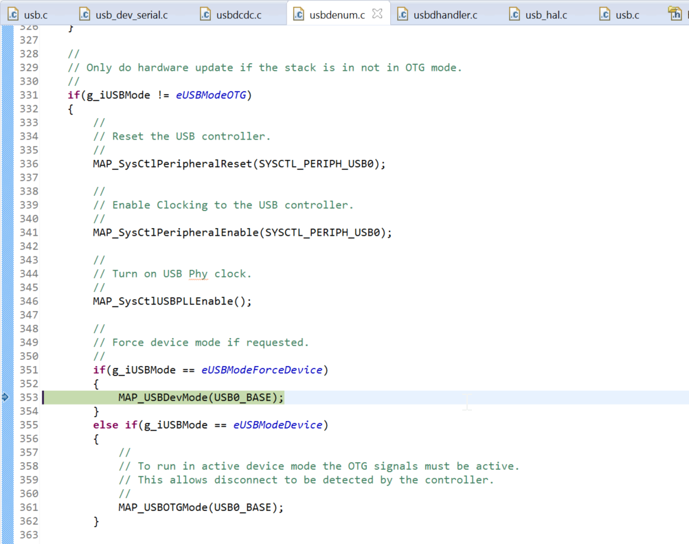
  • You can also look at the USBDCDInit() function in usbdenum.c.

    The device needs to be set up for OTG (which we do not support) in order to monitor VBUS and generate a DISCONNECT interrupt.