This thread has been locked.

If you have a related question, please click the "Ask a related question" button in the top right corner. The newly created question will be automatically linked to this question.

TMS320F28377D: Micro stuck in Bootrom code

Part Number: TMS320F28377D
Other Parts Discussed in Thread: C2000WARE

Hello, 

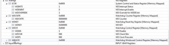
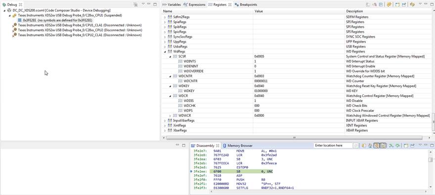
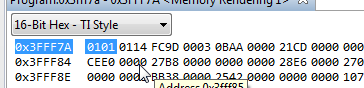
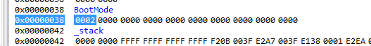
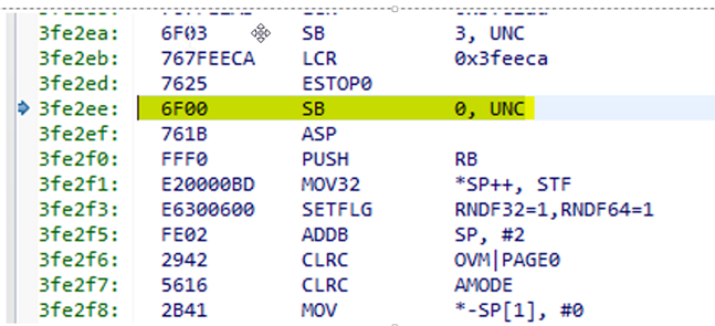
Microcontroller (F28377D) seems to be stuck in bootrom code. This is not normal behavior and can only be recreated by repeated resets through watchdog from application. Once the micro gets in this "Zombie" state, I was able to connect JTAG (modified gel to not change CPU state) and read registers and find the address (0x3fe2ee) it was stuck at. we can see its stuck at a branch unconditionally to the same place, in essence while 1. Attached CPU registers and a snapshot of bootrom code from disassembly view. Questions

  1. What are the conditions in bootrom that lead to this instruction?
  2. Why is watchdog not triggering? ( Is watchdog turned on in bootrom?

Register contents :/cfs-file/__key/communityserver-discussions-components-files/171/CCS_5F00_Export_5F00_PeripheralMap.txt

  • Hi Sandeep,

    Can you check the value of GPIO72/GPIO84 in this error condition. On every reset BOOTPIN values are sampled and if some time these values are not sampled correctly (due to noise or external driver) then device will not boot correctly.

    Regards,

    Vivek Singh
  • Sandeep,

    The location getting stuck is "wait boot". It is likely getting there due to some issues with the values on the boot mode selection pins as Vivek stated. Refer to the TRM or boot code source for details on the various flows that can lead to wait boot.

    If the OTP Boot Configure Word is programmed with a valid key, then it's possible to enter wait boot without enabling the watchdog. Default state of wait boot has watchdog enabled. Additionally, it's enabled before exiting boot.

    Best regards
    Chris
  • Boot pins (GPIO72 & GPIO84) are connected to 3.3V via 10kOhm resistors and are not used for any other purpose. Is 10kOhm too weak ?

    If I may label unit described in my question as unit_A, we have two more units in same situation. 

    Unit_B : seems to be stuck at 0x3FEFB3 address and loops between two instructions.

    And from registers it appears watchdog is disabled.

    We intentionally put a bench unit into "wait" mode by connecting GPIO84 to ground. Connected JTAG and could confirm it was stuck at 0x3fe2ee (just like in original question) also we can see watchdog is disabled.

    In these boards OTP boot configuration is not used and just left blank (will double check)

    Questions:

    1. It appears watchdog is disabled in "Wait" mode, please confirm.
    2. Is 10kOhm pull up on boot mode pins too weak? 

  • Sandeep,

    Yes, watchdog is disabled in wait boot.

    Value of resistance depends on what kind of noise we expect on the board. 10kOhm résistance value may not be enough for very noisy environment.

    Did you check the GPIO 72/84 value to make sure it is indeed because of wrong GPIO value ?

    Regards,

    Vivek Singh

  • Vivek, 

    Can you elaborate what you want me to check on GPIO 72/84. Do you want me to check on GPADAT register ? I suspect it will show as 1, will check to be sure. Bootrom could be reading it low due to  transient. Does bootrom store these pin sampled values in ram ? It can confirm cause of getting into "wait" mode.

    This situation does not happen every time, we have to run a overnight cycle of periodic resets and it will get into this state at some point.

    Thanks,

    Sandeep

  • Sandeep,

    The pins values aren't stored in RAM, they are sampled on each reset. If you are reusing the GPIOs, make sure you are holding them in the correct state for specified amount of time (~1.5ms).

    Best regards
    Chris
  • Sandeep,

    Also, you can double check what boot mode is being determined during boot by loading the ROM symbols from C2000Ware and using a target configuration that has no GEL scripts which reset the device on target connect. The BootMode global variable populated by boot is readable from RAM.

    Best regards
    Chris
  • Hi Chris,

    "BootMode" variable, this is exactly what I was asking for, awesome. How to find what version of boot rom code is on these chips? I see two versions in C2000Ware ver 0 and ver B. I cannot find a boot rom guide for F28377D like the one for TMS320x2834x www.ti.com/.../sprufn5b.pdf.

    Also, in case of Unit_B: Its stuck at a different location 0x3FEFB3, what location is this and how it could get here.

    Thanks,
    Sandeep
  • Sandeep

    All the boot details are in the TRM: www.ti.com/.../spruhm8
    The "wait points" section will tell you the common address ranges where boot can get stuck. It looks in the case of the address you just posted, you can waiting in "parallel boot".

    Check the boot ROM version, v1.1 is rev B and v1.0 is rev0. The memory location for this is in the TRM.

    Best regards
    Chris
  • Hi Chris, 

    I used search in acrobat  on the TRM, should have just looked through the boot section. The boot rom in these chips is Rev B and "BootMode" variable is at 02 and corresponds to "Wait" mode. This means when boot pins where sampled GPIO 84 was read low. Do you know from the power rails powering up what is the time when these pins are sampled ?  From TRM, these pins have pull up disabled at reset so its entirely dependent on the external pull up to set up boot mode.

    Thanks,

    Sandeep

  • Sandeep

    Yes, they rely on external pull up. They are sampled near the end of boot up. I don't have exact times though, as I mentioned, we recommend holding the boot GPIOs in the desired state for ~1.5ms starting from when device power up begins.

    Best regards
    Chris
  • Sandeep,

    I’m wondering whether 10k pull resistor might be too weak. Have you guys already tried 1K pull-up resistor? We can change boot mode pins but don’t have a way to directly boot to flash without boot mode pins on this device.

    Also, have made sure to boot pins are held in the right state for atleast 1.5ms?

    Regards,

    Manoj

  • Sandeep

    Edited: Another option to consider is programming the OTP location to use the same GPIO for each of the two boot GPIOs. This will essentially only require you to use one boot pin and then just put a strong pull on that. This will result in Get boot mode. 

    Best regards
    Chris

  • Sandeep

    Have you been able to try any of these suggestions? Has this been resolved?

    Best regards
    Chris
  • Hello All, 

    The issue is not resolved yet and we have tried many things. we tried 1K resistors and the issue would still occur.  Also the fact  we have to run the cyclic tests for over 36 hours sometimes to recreate make it very hard to diagnose. In one instance the issue could be recreated in minutes but once we changed bootloder (our bootloader code running in flash) to a different version to test and reverted back, since then unable to recreate on that unit. 

    We took the binky app from examples and enabled watchdog so it keeps resetting, ran it on 5 units for over 15 hours and could not recreate issue. So far from our tetsing we can see our test of repeated firmware download (and and then watchdog reset) seems to make this issue occur. Is there anything in Flash erase/ program that could cause this ?

    we are setting up few units that have exhibited this issue at least once as a test farm and use it to run tests so we can increase our chances of recreating issue.

    Thanks,

    Sandeep 

  • Sandeep,

    I don't see how repeated firmware download would cause this behavior. Knowing answers to these questions may help narrow down the problem. Can you please look into this?

    1) Are you using boot mode pins in your application code?
    2) Did you already try not using boot mode pins in your application code?
    3) Is the flash erased when you see the problem?
    4) Once you see the problem? Are you able to re-produce repeatedly?

    Regards,
    Manoj
  • HI Manoj, 

    1) Are you using boot mode pins in your application code? No, the pins are pulled up to 10K and not connected or used for any purpose
    2) Did you already try not using boot mode pins in your application code? Bootmode pins are configured for input with pull up
    3) Is the flash erased when you see the problem? I will have to check on notes, will get back.
    4) Once you see the problem? Are you able to re-produce repeatedly? Takes a long time, sometimes as long as 24 hours of repeated cycling of firmware download at rate of once a minute.


  • Sandeep,
    Also please if you can monitor VDDIO as well to see if there is a drop when the error happens?

    Best Regards
    Santosh Athuru
  • we had scope on the two boot select GPIO pins and caught the instance where bootrom selected a different mode. The traces were solid line and didnt show any glitches so the 3.3V rail was solid.

    Sandeep