This thread has been locked.

If you have a related question, please click the "Ask a related question" button in the top right corner. The newly created question will be automatically linked to this question.

F28M35H52C: Concerto : Read ADC1A and ADC1B all channels using PWMSOCA and PWMSOCB

Part Number: F28M35H52C


Hello,

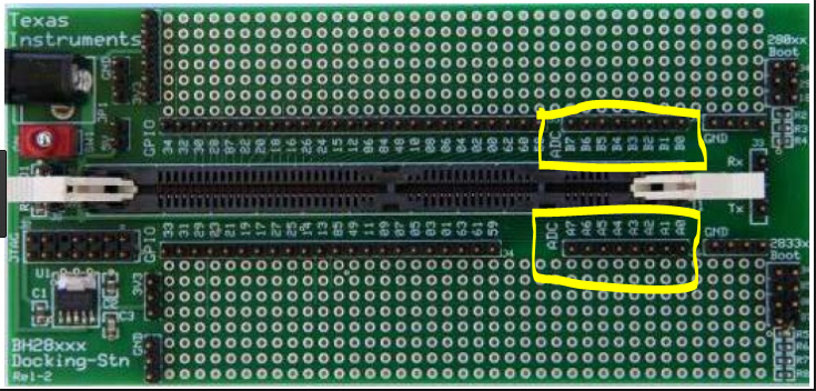
i am trying to initialize all ADC channels of ADC1 to read analog signals of concerto, for start of conversion i am using PWM SOCA and SOCB. i have referred adc_soc example code to do this. but facing issues while reading ADC1B 8 channels. Can anyone please help

  • Hi,

    Have you configured the GPIO settings as required? Can you provide us more details on the issue you are facing? If possible, provide us the code snippet of how the configuration is done.

    Thanks and Regards,
    Veena
  • Hi Veena,

    below is the code, main function is not written over here,only ADC configuration, ADC enable and ADC isr is written. Also in below code, for 15 channels of ADC1 i have configured same PWM trigger SOCA. After running this example i am able to get data in only ADC1A channels. from channel 8 to 15 i am not getting any values. i have applied  voltage from 0 to 3.3 on these analog inputs. please let me know if i am making any mistake while initializing. 

    Uint16 ConversionCount;
    Uint16 adc1Voltage_ChannelA0[10];
    Uint16 adc1Voltage_ChannelA2[10];

    Uint16 adc1Voltage_ChannelA3[10];
    Uint16 adc1Voltage_ChannelA4[10];

    Uint16 adc1Voltage_ChannelA6[10];
    Uint16 adc1Voltage_ChannelA7[10];

    Uint16 adc1Voltage_ChannelB0[10];
    Uint16 adc1Voltage_ChannelB3[10];

    Uint16 adc1Voltage_ChannelB4[10];
    Uint16 adc1Voltage_ChannelB7[10];

    void adcConfig()

    {

    // GPIO configuration

    GpioG1CtrlRegs.GPADIR.bit.GPIO0 = 1; //Set as output

    GpioG1CtrlRegs.GPADIR.bit.GPIO8 = 1; //Set as output

    GpioG1CtrlRegs.GPAMUX1.bit.GPIO0 = 1; //Set mux to EPWM1A
    GpioG1CtrlRegs.GPAMUX1.bit.GPIO8 = 3; //Set mux to ADCSOCAn

    // interrupt assigned to Pie vector table

     PieVectTable.ADCINT1 = &adc1_isr;

    // ADC1 enable

    EALLOW;
    Adc1Regs.ADCCTL1.bit.ADCBGPWD = 1; // Power ADC1 BG
    Adc1Regs.ADCCTL1.bit.ADCREFPWD = 1; // Power reference
    Adc1Regs.ADCCTL1.bit.ADCPWDN = 1; // Power ADC1
    Adc1Regs.ADCCTL1.bit.ADCENABLE = 1; // Enable ADC1
    Adc1Regs.ADCCTL1.bit.ADCREFSEL = 0; // Select interal BG
    EDIS;

     DELAY_US(ADC_usDELAY);  

    // PIE and CPU interrupt Enable

    PieCtrlRegs.PIEIER1.bit.INTx1 = 1;                       // Enable INT 1.1 in the PIE

    IER |= M_INT1;                                                       // Enable CPU Interrupt 1


    // Configure ADC
    EALLOW;

    Adc1Regs.ADCCTL2.bit.ADCNONOVERLAP = 1;                 // Enable non-overlap mode i.e.
    Adc1Regs.ADCCTL1.bit.INTPULSEPOS = 1;                        // ADCINT1 trips after AdcResults latch

    // Enabled ADCINT1

    Adc1Regs.INTSEL1N2.bit.INT1E = 1; // Enabled ADCINT1
    Adc1Regs.INTSEL1N2.bit.INT1CONT = 0; // Disable ADCINT1 Continuous mode
    Adc1Regs.INTSEL1N2.bit.INT1SEL = 15; // setup EOC15 to trigger ADCINT1 to fire

    //Select ADC input channels

    Adc1Regs.ADCSOC0CTL.bit.CHSEL = 0; 
    Adc1Regs.ADCSOC1CTL.bit.CHSEL = 1; 
    Adc1Regs.ADCSOC2CTL.bit.CHSEL = 2; 
    Adc1Regs.ADCSOC3CTL.bit.CHSEL = 3; 
    Adc1Regs.ADCSOC4CTL.bit.CHSEL = 4; 
    Adc1Regs.ADCSOC5CTL.bit.CHSEL = 5;
    Adc1Regs.ADCSOC6CTL.bit.CHSEL = 6; 
    Adc1Regs.ADCSOC7CTL.bit.CHSEL = 7; 
    Adc1Regs.ADCSOC8CTL.bit.CHSEL = 8; 
    Adc1Regs.ADCSOC9CTL.bit.CHSEL = 9; 
    Adc1Regs.ADCSOC10CTL.bit.CHSEL = 10; 
    Adc1Regs.ADCSOC11CTL.bit.CHSEL = 11; 
    Adc1Regs.ADCSOC12CTL.bit.CHSEL = 12; 
    Adc1Regs.ADCSOC13CTL.bit.CHSEL = 13; 
    Adc1Regs.ADCSOC14CTL.bit.CHSEL = 14; 
    Adc1Regs.ADCSOC15CTL.bit.CHSEL = 15;

    AnalogSysctrlRegs.TRIG1SEL.all = 5;                        // Assigning EPWM1SOCA to ADC TRIGGER 1 of the ADC module

    Adc1Regs.ADCSOC0CTL.bit.TRIGSEL = 5;
    Adc1Regs.ADCSOC1CTL.bit.TRIGSEL = 5; 
    Adc1Regs.ADCSOC2CTL.bit.TRIGSEL = 5; 
    Adc1Regs.ADCSOC3CTL.bit.TRIGSEL = 5; 
    Adc1Regs.ADCSOC4CTL.bit.TRIGSEL = 5; 
    Adc1Regs.ADCSOC5CTL.bit.TRIGSEL = 5; 
    Adc1Regs.ADCSOC6CTL.bit.TRIGSEL = 5; 
    Adc1Regs.ADCSOC7CTL.bit.TRIGSEL = 5; 
    Adc1Regs.ADCSOC8CTL.bit.TRIGSEL = 5; 
    Adc1Regs.ADCSOC9CTL.bit.TRIGSEL = 5; 
    Adc1Regs.ADCSOC10CTL.bit.TRIGSEL = 5;
    Adc1Regs.ADCSOC11CTL.bit.TRIGSEL = 5; 
    Adc1Regs.ADCSOC12CTL.bit.TRIGSEL = 5;
    Adc1Regs.ADCSOC13CTL.bit.TRIGSEL = 5;
    Adc1Regs.ADCSOC14CTL.bit.TRIGSEL = 5; 
    Adc1Regs.ADCSOC15CTL.bit.TRIGSEL = 5; 

    // Set S/H window of 7 ADC clock cycles
    Adc1Regs.ADCSOC0CTL.bit.ACQPS = 6;          // S/H = ACQPS + 1
    Adc1Regs.ADCSOC1CTL.bit.ACQPS = 6;         // S/H = ACQPS + 1
    Adc1Regs.ADCSOC2CTL.bit.ACQPS = 6;        // S/H = ACQPS + 1
    Adc1Regs.ADCSOC3CTL.bit.ACQPS = 6;       // S/H = ACQPS + 1
    Adc1Regs.ADCSOC4CTL.bit.ACQPS = 6;       // S/H = ACQPS + 1
    Adc1Regs.ADCSOC5CTL.bit.ACQPS = 6;       // S/H = ACQPS + 1
    Adc1Regs.ADCSOC6CTL.bit.ACQPS = 6;       // S/H = ACQPS + 1
    Adc1Regs.ADCSOC7CTL.bit.ACQPS = 6;       // S/H = ACQPS + 1
    Adc1Regs.ADCSOC8CTL.bit.ACQPS = 6;       // S/H = ACQPS + 1
    Adc1Regs.ADCSOC9CTL.bit.ACQPS = 6;       // S/H = ACQPS + 1
    Adc1Regs.ADCSOC10CTL.bit.ACQPS = 6;     // S/H = ACQPS + 1
    Adc1Regs.ADCSOC11CTL.bit.ACQPS = 6;     // S/H = ACQPS + 1
    Adc1Regs.ADCSOC12CTL.bit.ACQPS = 6;    // S/H = ACQPS + 1
    Adc1Regs.ADCSOC13CTL.bit.ACQPS = 6;    // S/H = ACQPS + 1
    Adc1Regs.ADCSOC14CTL.bit.ACQPS = 6;    // S/H = ACQPS + 1
    Adc1Regs.ADCSOC15CTL.bit.ACQPS = 6;    // S/H = ACQPS + 1

    EDIS;

    //// Assumes ePWM1 clock is already enabled in InitSysCtrl();

    //Set event triggers (SOCA) for ADC SOC1


    EPwm1Regs.ETSEL.bit.SOCAEN = 1; // Enable SOC on A group
    EPwm1Regs.ETSEL.bit.SOCASEL = ET_CTRU_CMPA; // Select SOC from CMPA on upcount
    EPwm1Regs.ETPS.bit.SOCAPRD = 3; // Generate pulse on every 3rd// event

    // Time-base registers

    EPwm1Regs.TBPRD = 1000;           // Set timer period, PWM frequency = 1 / period
    EPwm1Regs.TBPHS.all = 0;             // Time-Base Phase Register
    EPwm1Regs.TBCTR = 0;                  // Time-Base Counter Register
    EPwm1Regs.TBCTL.bit.PRDLD = TB_IMMEDIATE;              // Set Immediate load
    EPwm1Regs.TBCTL.bit.CTRMODE = TB_COUNT_UP;              // Count-up mode: used for asymmetric PWM
    EPwm1Regs.TBCTL.bit.PHSEN = TB_DISABLE;                        // Disable phase loading
    EPwm1Regs.TBCTL.bit.SYNCOSEL = TB_SYNC_DISABLE;
    EPwm1Regs.TBCTL.bit.HSPCLKDIV = TB_DIV1;
    EPwm1Regs.TBCTL.bit.CLKDIV = TB_DIV1;

    // Setup shadow register load on ZERO

    EPwm1Regs.CMPCTL.bit.SHDWAMODE = CC_SHADOW;
    EPwm1Regs.CMPCTL.bit.SHDWBMODE = CC_SHADOW;
    EPwm1Regs.CMPCTL.bit.LOADAMODE = CC_CTR_ZERO; // load on CTR=Zero
    EPwm1Regs.CMPCTL.bit.LOADBMODE = CC_CTR_ZERO; // load on CTR=Zero

    // Set Compare values

     EPwm1Regs.CMPA.half.CMPA = 500;    // Set duty 50% initially
    EPwm1Regs.CMPB = 500;                    // Set duty 50% initially

    // // Set actions
    EPwm1Regs.AQCTLA.bit.ZRO = AQ_SET;                   // Set PWM2A on Zero
     EPwm1Regs.AQCTLA.bit.CAU = AQ_CLEAR;            // Clear PWM2A on event A, up count
     EPwm1Regs.AQCTLB.bit.ZRO = AQ_CLEAR;            // Set PWM2B on Zero
     EPwm1Regs.AQCTLB.bit.CBU = AQ_SET;                 // Clear PWM2B on event

    }

    __interrupt void adc1_isr(void)
    {


    adc1Voltage_ChannelA0[ConversionCount] = Adc1Result.ADCRESULT0;
    adc1Voltage_ChannelA2[ConversionCount] = Adc1Result.ADCRESULT2;

    adc1Voltage_ChannelA3[ConversionCount] = Adc1Result.ADCRESULT3;
    adc1Voltage_ChannelA4[ConversionCount] = Adc1Result.ADCRESULT4;

    adc1Voltage_ChannelA6[ConversionCount] = Adc1Result.ADCRESULT6;
    adc1Voltage_ChannelA7[ConversionCount] = Adc1Result.ADCRESULT7;

    adc1Voltage_ChannelB0[ConversionCount] = Adc1Result.ADCRESULT8;
    adc1Voltage_ChannelB3[ConversionCount] = Adc1Result.ADCRESULT11;

    adc1Voltage_ChannelB4[ConversionCount] = Adc1Result.ADCRESULT12;
    adc1Voltage_ChannelB7[ConversionCount] = Adc1Result.ADCRESULT15;

    if(ConversionCount == 9)

    {

    ConversionCount = 0;
    }
    else ConversionCount++;

    Adc1Regs.ADCINTFLGCLR.bit.ADCINT1 = 1; //Clear ADCINT1 flag reinitialize
    // for next SOC
    PieCtrlRegs.PIEACK.all = PIEACK_GROUP1; // Acknowledge interrupt to PIE

    return;
    }

  • Hi Sandeep,

    Apologies for the delay. I was unable to reproduce the issue.
    I used the code provided in this thread and I was able to read all the ADC result registers. From what I understood, you were able to hit the ADC ISR but the result registers for channels 8-15 are 0. Is that right?
    Can you also provide more details on which board you are using? Have you connected the ADC pins to some signals or are they floating?

    Thanks and Regards,
    Veena
  • Sorry, actually it was my fault of testing. From concerto control card to docking station total 16 connections are coming, ADC1A -6 channels and ADC1B - 2 channels are mapped on A0 to A7 pins(J6 connector) of ADC on docking station also from ADC2A- 6 channels and ADC2B- 2 channels are mapped on B0 to B7 pins(J7 connector) of ADC on docking station.

    And i was thinking that only one ADC that is ADC1 16 channels are coming on to docking station. because of that i was applying signal to wrong pins that is on B0 to B7 by considering it as ADC1B 8 to 15 channel. i got confused because of naming on docking station A0 to A7 and B0 to B7.

    Now issue is resolved, after going through schematics of Docking station and Concerto card. Thanks for your help.

    Regards,
    Sandeep
  • Sandeep,

    sorry for the confusion, I see how this could be frustrating. Where did you find the "naming on docking station A0 to A7 and B0 to B7."? I will try to make this more clear for other users of the Concerto controlCARD.

    I'm glad you found the solution, the assumptions we make can cause the simplest things to be the hardest to find.

    Regards,
    Cody 

  • Hello Cody,

    As i mentioned, you can find ADC A0 to A7 and B0 to B7 connections on docking station. 

  • Sandeep,

    Ah, OK! So you are using the 180 to 100 Pin DIMM Adapter? The newer 180 pin version of the controlCARD dock has revised this labeling.

    We won't be able to update the labeling on the DIMM 100 dock itself because it is still accurate for many of the DIMM 100 controlCARDs. None the less I will see if I can add something to the documentation to make this more clear.

    Thanks for you input!
    Cody