Tool/software: Code Composer Studio
Hello,
My colleague and I are trying to implement 12 channels of EPWM in TMS320F28379D. In the beginning of the main function, we called the EPWM initialization functions from "InitEPwm1Gpio()" to "InitEPwm12Gpio()" which are defined in "F2837xD_EPwm.c". However, the test result shows that only EPWM1 to EPWM8 can work whereas EPWM9 to EPWM12 cannot work. We therefore dig into "F2837xD_EPwm.c" and try to find out why.
In the datasheet, either GPIO0 or GPIO145 can be defined as EPWM1A, and either GPIO1 or GPIO146 can be defined as EPWM1B. In "F2837xD_EPwm.c", we can choose either of the two. The same applies to EPWM2 until EPWM8.
void InitEPwm1Gpio(void)
{
    EALLOW;

    GpioCtrlRegs.GPAPUD.bit.GPIO0 = 1;    // Disable pull-up on GPIO0 (EPWM1A)
    GpioCtrlRegs.GPAPUD.bit.GPIO1 = 1;    // Disable pull-up on GPIO1 (EPWM1B)
    // GpioCtrlRegs.GPEPUD.bit.GPIO145 = 1;    // Disable pull-up on GPIO145 (EPWM1A)
    // GpioCtrlRegs.GPEPUD.bit.GPIO146 = 1;    // Disable pull-up on GPIO146 (EPWM1B)

    GpioCtrlRegs.GPAMUX1.bit.GPIO0 = 1;   // Configure GPIO0 as EPWM1A
    GpioCtrlRegs.GPAMUX1.bit.GPIO1 = 1;   // Configure GPIO1 as EPWM1B
    // GpioCtrlRegs.GPEMUX2.bit.GPIO145 = 1;   // Configure GPIO145 as EPWM1A
    // GpioCtrlRegs.GPEMUX2.bit.GPIO146 = 1;   // Configure GPIO0146 as EPWM1B

    EDIS;
}
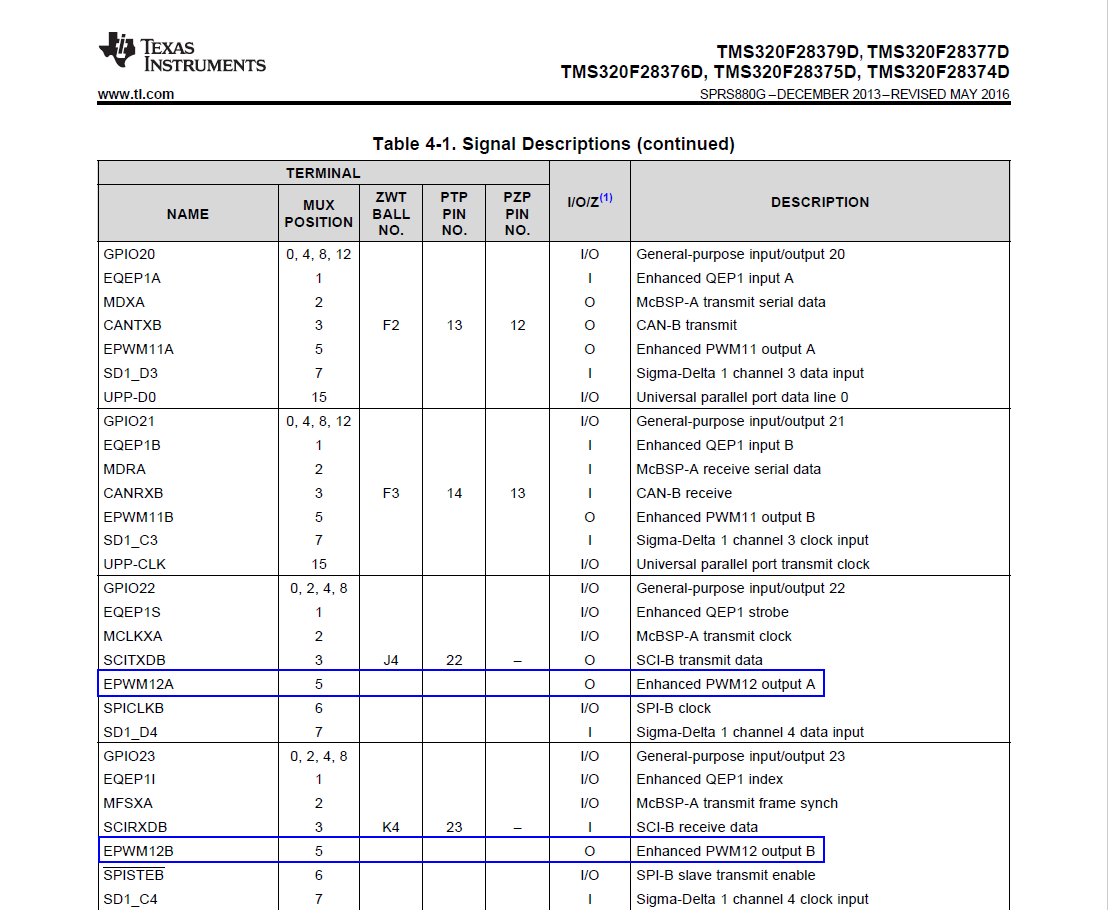
However, from EPWM9 to EPWM12, we have only one choice in "F2837xD_EPwm.c". From the datasheet, EPWM12A can be activated at either GPIO22 or GPIO167, but it is only possible at GPIO167 in the function:
void InitEPwm12Gpio(void)
{
    EALLOW;

    GpioCtrlRegs.GPFPUD.bit.GPIO167 = 1;    // Disable pull-up on GPIO167 (EPWM12A)
    GpioCtrlRegs.GPFPUD.bit.GPIO168 = 1;    // Disable pull-up on GPIO168 (EPWM12B)

    GpioCtrlRegs.GPFMUX1.bit.GPIO167 = 1;   // Configure GPIO167 as EPWM12A
    GpioCtrlRegs.GPFMUX1.bit.GPIO168 = 1;   // Configure GPIO168 as EPWM12B

    EDIS;
}
We want to activate it at GPIO22 because it is easier for the connection, and therefore we changed the code to be:
GpioCtrlRegs.GPAPUD.bit.GPIO22 = 1;    // Disable pull-up on GPIO22 (EPWM12A)
GpioCtrlRegs.GPAPUD.bit.GPIO23 = 1;    // Disable pull-up on GPIO23 (EPWM12B)

GpioCtrlRegs.GPBMUX2.bit.GPIO22 = 5;   // Configure GPIO22 as EPWM12A
GpioCtrlRegs.GPBMUX2.bit.GPIO23 = 5;   // Configure GPIO23 as EPWM12B
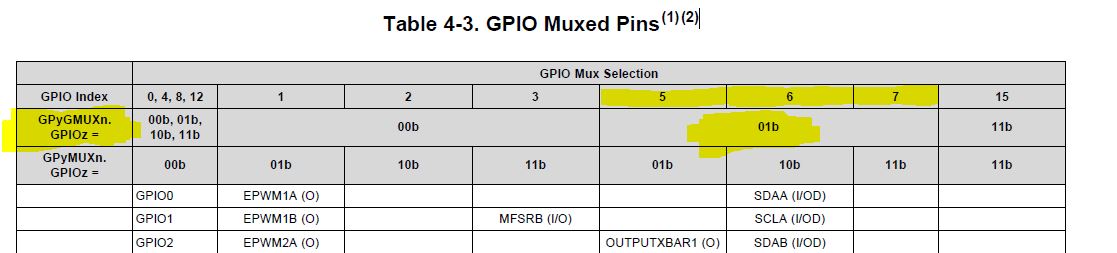
We change GPEMUX2 to GPBMUX2 because we see that in "F2837xD_gpio.h" GPIO22 and GPIO23 belong to GPBMUX2. The reason to assign "5" to the register instead of "1" is that in the datasheet, the mux should be set to 5 to activate EPWM12A and B:
However this does not really work because only 2 bits are defined in GPBMUX2 but the number 5 needs 3 bits: 101.
Then, why "F2837xD_gpio.h" only considers one of the pins for EPWM 8 to 12, and how to overcome this problem? Should we change "F2837xD_gpio.h"? Maybe TI will publish a new version of "F2837xD_gpio.h" soon?
Thank you very much!
Junfei Tang