This thread has been locked.

If you have a related question, please click the "Ask a related question" button in the top right corner. The newly created question will be automatically linked to this question.

TMS320F2811: ADC non-linearity

Part Number: TMS320F2811


I have some problem with TMS320F2811, about 40% of the production batch present a major non-linearity on the ADC reading.

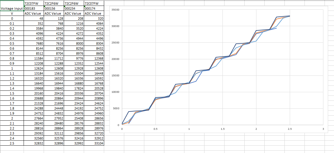
See the following graph below:

All the bad PCBs have the exact same behaviour. We have the same software on each PCB (good and bad). The hex value are coming directly from the ADCRESULT5 register through the debugger (12 bits).

What can explain that ?

Thanks,

Marc

  • Mark,

    I don't think that I have seen this behavior before.  Are you able to scope the input signal near the ADC pin to to make sure that there isn't some component that might be distorting the signal?

    Can you describe how many failures there are relative to the number of good PCBs ever built?  For example, would this be something like 20 failures versus a few hundred good builds?

    Are you able to swap F2811 devices between good and bad boards to confirm that the failure is caused by the F2811?

    -Tommy

  • Hi Tom,

    For your information:

    Part/lot number: TMS320F2811PBKA CG-72C2F6W we have a failure rate of about 60%

    Part/lot number: TMS320F2811PBKA CG-72C07FW we have a failure rate of about 10%

    Yes I probe the signal at the input pin and it is correct. There is only a RC filter between the DC source (Voltage Calibrator REED R8801) and the DSP.

    Right now with about 160 board programmed we have 61 with the non-linearity problem. We have another 200 to be programmed next week.

    Yes I will swap the F2811 device on a bad board. We ordered a new batch of F2811 with different lot number to do the swap.

    Thanks,

    Marc

  • We replace 4 DSP on PCB. Here is the result before:

    And after DSP replacement on the same board

    Which lot/batch can be affected with this problem ?

    Thank you,

    Mark

  • Marc,

    Thank you for performing the experiment. Can you confirm that the ADC clock is configured to between 1MHz and 25MHz?

    If the clock configuration is within that range, I would recommend contacting your distributor or local TI sales office to return some of the suspect units back to TI for evaluation. This behavior is not expected so I cannot offer an explanation for why those devices have such poor linearity.

    -Tommy