This thread has been locked.

If you have a related question, please click the "Ask a related question" button in the top right corner. The newly created question will be automatically linked to this question.

F28M35H52C: Concerto Remote Firmware update options

Part Number: F28M35H52C

Hello,

Wanted to start a new forum thread in regards to exploring ways in which we can update firmware remotely on Cortex M3 and C28 cores for concerto family of controllers. 

Currently on cortex m3 we have developed a simple second stage bootloader which gets executed after the BOOT ROM in cortex m3 ends its execution. As of now this bootloader just does a simple jump to the application program stored at a different memory section in the M3 flash. So as a future implementation we will have ways to check for application firmware upgrade serially in this bootloader before we make a jump to this application code. 
 
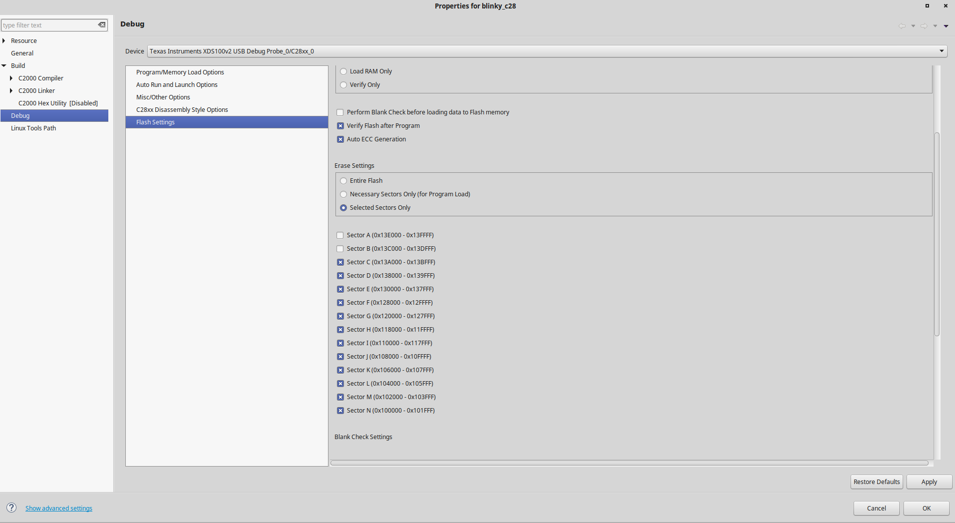
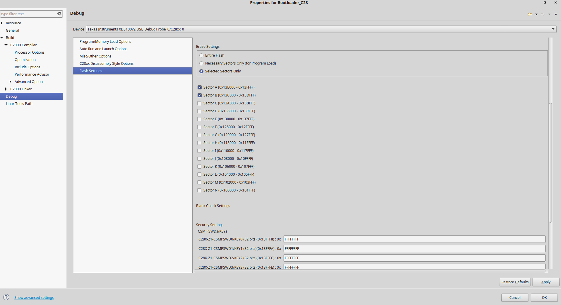
But the challenge now is to explore ways in which we can upgrade C28 application code remotely. So this is where we would require some help from TI. I have pointed out some options that we thought could be possible. But can you please confirm us if any one of these works or if not please guide us through the rite direction. 
 
1. Firstly we need some clear understanding on how the memory mapping is done on the entire Concerto Microcontroller {How M3 and C28 share the memory}, it would be great if someone can point out the rite
    sections in the concerto reference manual. 
 
Option one :
 
To update C28 application flash section through IPC mechanism when inside M3 bootloader.
 
Option two:
 
To have a separate serial I/O pins for M3 and C28 which can be triggered for a firmware update separately.  
 
Final Option:
 
Here we thought of updating the way its currently done on the Concerto Evaluation board. Where we will have a FTDI chip which would update M3 and C28 separately using USB. I guess this requires some FLASH algorithm to be shared from TI.
 
Please let me know if we need to have a call next week. 
 
Thanks   
  • Preetham,

    For the first question:

    On Concerto each subsystem (M3 and C28x) have their own memories. You can refer to the device data sheet which has detailed memory map. In addition to the dedicated memories there is shared RAM which is owned by master (M3) on reset or by default and can be configured to C28x subsystem by the master. There are also message ram blocks which can be used to pass on information from master to control (C28x) subsystem and vice versa. In addition to share RAM and message RAMs there is IPC (inter process communication) which is basically a set of registers for user SW to implement a command<->response system or message passing system between the cores.

    Datasheet is the first document to start looking at , understanding the block diagram and memory map and then you can move onto the system control and the boot ROM chapters of the device TRM to understand how the device starts up.

    For the FW upgrade design, there are other users who implemented this on Concerto (F28M35x and F28M36x), there are also 3rd party vendors (BPMicro) who supply production programming solutions for Concerto. 

    Below is an outline on how you can design a FW upgrade system on Concerto.

    You can get started with control suite examples (flash API, blinky), but we don’t have an example which has below as it is yet.

    You would need M-Kernel (running on M3) and C-Kernel (running on C28x), these kernels get downloaded on to respective cores using the one of the boot options supported by device boot ROM  (refer to device TRM for boot mode(s) on M3 and IPC Boot command(s) on C28x), also these kernels will have needed F021 flash API for the respective core. Once these kernels get loaded they take over the boot peripheral and download the application and flash the downloaded application.

     So the kernels will have two parts, reading application (parsing the incoming data) from the boot peripheral and the Flash API to flash the downloaded application.

    1.>   On power up you would select a boot mode using the boot mode GPIO, this will put the M-Boot ROM in Parallel GPIO boot mode or UART boot etc.

    2.>   Now you will send the M-Kernel which has the flash API and functions to read the data from boot peripheral.

    3.>   Once the M-Kernel is downloaded on to M3 RAMs, boot ROM will start this kernel.

    4.>   Now, the M-Kernel should have two modes.

    1. Mode 1: download and update M3 application in M3 Flash.
    2. Mode 2: kick start the boot loader on C-Boot ROM by sending the supported IPC Command to C-Boot ROM.

    5.>   Once the M-Kernel kick starts the boot loader (parallel or SCI etc) on C-Boot ROM, the C-Boot ROM is ready to receive the C-Kernel via the selected boot peripheral pins.

    6.>   Now Host sends the C-Kernel to C-Boot ROM. This C-Kernel has the Flash API needed and functions to read application from the boot peripheral on C28.

    7.>   Once the C-Kernel is started it will begin downloading the application and flash the application, the M-Kernel is IDLE while C-Kernel is doing this. On the other hand while M-Kernel is downloading the application the C28x is still running its boot ROM and is in low power IDLE mode.

    If using Parallel boot:-

    Same IO pins are supported on both M-Boot ROM and C-Boot ROM parallel IO mode and the data protocol format is similar to that of earlier C28x devices. Please refer to the boot ROM chapter on the device TRM for more details. Just like hex2000 for C28x there is ARMHEX which converts the COFF to HEX for M3 side.

    The kernels should be linked such that they will run from RAM, the downloaded application should have the entry point linked to FLASH ENTRY POINT, so that the application is started when boot to flash is selected using the boot mode pins.

    For using UART :-

    You could follow similar kernel design if you want to support SCI/UART and with UART boot if you don’t want to connect two physical DB9 connectors then you can use SERPLOOP feature to loopback UART4 on M3 to SCIA on C28x and boot from that SCIA. The M-kernel in this case will act as a bridge passing on data between UART4 and UART0.

    If you don't want to use or cannot use any of the provided C-Boot ROM peripheral boot mode(s) then you will have to design a C-kernel that can get loaded to C28 RAM using shared RAM(s) and IPC and the C-Kernel running from shared RAM (assigned to C28) can read the C-application and flash it in C28x flash using message RAM(s) and IPC.

    On the last question you had:

    Using FTDI and using USB port, you will not be able to include this into your application for doing an in-application FW upgrade. This option should be good for production programming depending on how you design the line but for FW upgrade this is not a good option. 

    [edit:- as mentioned above, if you are also looking for production programming solution, refer to BP Micro]

    Refer to the device TRM boot ROM chapter, you will have to understand the boot flow, boot modes supported, how the C28x subsystem boots and what it supports and then choose which HW peripheral you will use for boot and FW upgrade and proceed with FW upgrade kernel(s) design.

    Hope this helps. Please let us know if you have any further questions.

    Best Regards
    Santosh Athuru 

  • Hi Santosh,

    Thanks for first hand comprehensive reply. 

    I will work on your suggestions and get back to you once i have more clarity. 

    1. Meanwhile can you please clarify what do you mean by M3 and C28 kernel ? are you implying about having our own separate M3 and C28 boot-loader application ?

    2. Also when you say we need to download the M3 kernel in to the RAM using M3 BOOT ROM serial download, do you mean this is only option or is this one of the option you suggested ? 

    Because i was thinking of flashing a bootloader application in a separate M3 flash sector and C28 flash sector and then have the BOOT ROM'S to boot to this flash based bootloader and then check for firmware upgrade !! I believe this can be possible but can you please suggest if this works ? 

    Thanks 

  • Preetham,

    Preetham kashyap said:
    1. Meanwhile can you please clarify what do you mean by M3 and C28 kernel ? are you implying about having our own separate M3 and C28 boot-loader application ?

    yes, you will need to have your own kernel (or boot loader application in your terminology) that parses the incoming application that needs to be flashed. The SW component that includes the boot peripheral read, parsing of incoming data, flashing of the application, synchronizing the communication between the device and HOST that is sending the application are some of the basic components of what I was referring to.

    Preetham kashyap said:
    2. Also when you say we need to download the M3 kernel in to the RAM using M3 BOOT ROM serial download, do you mean this is only option or is this one of the option you suggested ? 

    on above, yes I was taking an example of one possible way. Depending on the boot options you choose you will be downloading the kernel/boot-loader to RAMs using that peripheral boot. Refer to TRM boot ROM section on the available boot modes.

    Preetham kashyap said:
    Because i was thinking of flashing a bootloader application in a separate M3 flash sector and C28 flash sector and then have the BOOT ROM'S to boot to this flash based bootloader and then check for firmware upgrade !! I believe this can be possible but can you please suggest if this works ? 

    Yes, this is absolutely possible. You can have your kernels/boot-loaders in flash sectors and have each core boot to flash and the boot-loaders will download the application on to respective flash. I just gave an example where if you don;t have the kernels/boot-loaders in flash already then you can download them using the existing ROM loaders.

    Hope this helps, please let us know if you have further questions.

    Best Regards

    Santosh Athuru

  • Moderator Note: separate question split off to own thread here:
    e2e.ti.com/.../653644
  • Hi Santosh,

    Need to get few things clarified. 

    I have a simple M3 and C28 Bootloader  which i have programmed in Flash sections of the M3 and C28 respectively, rather than have it run from RAM.

    For doing this i have used CCS provided debug options from the project properties dialog, where user is allowed to program for selected Flash sectors.  

    So for M3 Bootloader i have used FLASH sectors N and M. For M3 Application program (blinky) i have used the remaining apart from N and M starting from 0x00208000. With this setting i am able to now flash M3 Bootloader and M3 application separately and i can have both bootloader and application work in stand alone mode as well. Meaning i can retain two different programs in two different sections of M3 Flash. 

    But the challenge is now pertaining to C28 core, where i am trying to do same as above and i am having issues retaining the C28 application program in flash. i have used C28 flash sectors A and B for Bootloader and remaining  sectors for C28 application (blinky) program. 

    I am actually trying to send a IPC command from M3 Bootloader to C28 Bootloader to have C28 come out of idle state and progress to C28 application program and thereby allowing M3 bootloader to jump to M3 application program. 

    The challenge is flashing two different flash sectors of C28, so that i can have Bootloader in some specific sectors and C28 application program in other specific sectors ? 

    Can you please provide me some hints on how i can achieve the above ?? 

    Thanks

  • Preetham,

    What do you mean by not able to retain the application in C28x Flash memory? Can you provide more details?

    Thanks and regards,
    Vamsi
  • Hi Vamshi,

    So the below screen shots should suggest you what i am trying to do :

    1. Primarily i am trying to first flash the C28 Blinky application starting from 0x13A000 Flash sector C. 

    2. Secondly i will try and flash the C28 Bootloader application to which i have assigned Flash Sectors A and B (0x13E000 - 0x13DFFF).

     So its during my second step that i am having issues. I expect only FLASH sectors A and B getting erased and programmed, but instead its erasing all the other FLASH sectors too which is intern erasing my previously programmed application.  How could i avoid this from happening ?

    Thanks 

  • Preetham,

    Can you try below steps and see if it works for you?

    (1) Don't use project properties to configure the Flash settings. Instead use the below mentioned path to find the Flash settings GUI.
    (2) Erase all the sectors first using the On-Chip Flash GUI (CCS Debug window -> Tools -> On-Chip Flash)
    (3) Then, in the GUI, use "Program Only" option instead of "Erase and Program" option.
    (4) Load your application
    (5) Load your bootloader

    Thanks and regards,
    Vamsi
  • Hi Vamsi,

    Thanks for the steps....I had to perform the reverse of what you mentioned. Basically i selected the FLASH sectors i want to program for that particular application using the GUI you mentioned and performed Erase and Program instead of program only. 

    Now i have some questions regrading FLASH API applications, could i continue posting those here or should i create a different post for it on e2e ??

  • Preetham,

    Glad that those steps helped you to experiment and get you where you want.

    Regarding Flash API questions: Please review below resources and then post your questions in a new post in E2E.

    (i) http://www.ti.com/lit/pdf/spnu595

    (ii) http://processors.wiki.ti.com/index.php/C2000_Flash_FAQ  

    Thanks and regards,

    Vamsi

  • Hi Vamsi,

    I have already gone through the application note before considering Flash API in the code. But facing some challenges with Erasing the FLASH sectors on M3. 

    As you suggested i will post my question in a new thread.

    Thanks