This thread has been locked.

If you have a related question, please click the "Ask a related question" button in the top right corner. The newly created question will be automatically linked to this question.

TMS320F28335: f28335

Part Number: TMS320F28335


Hello,

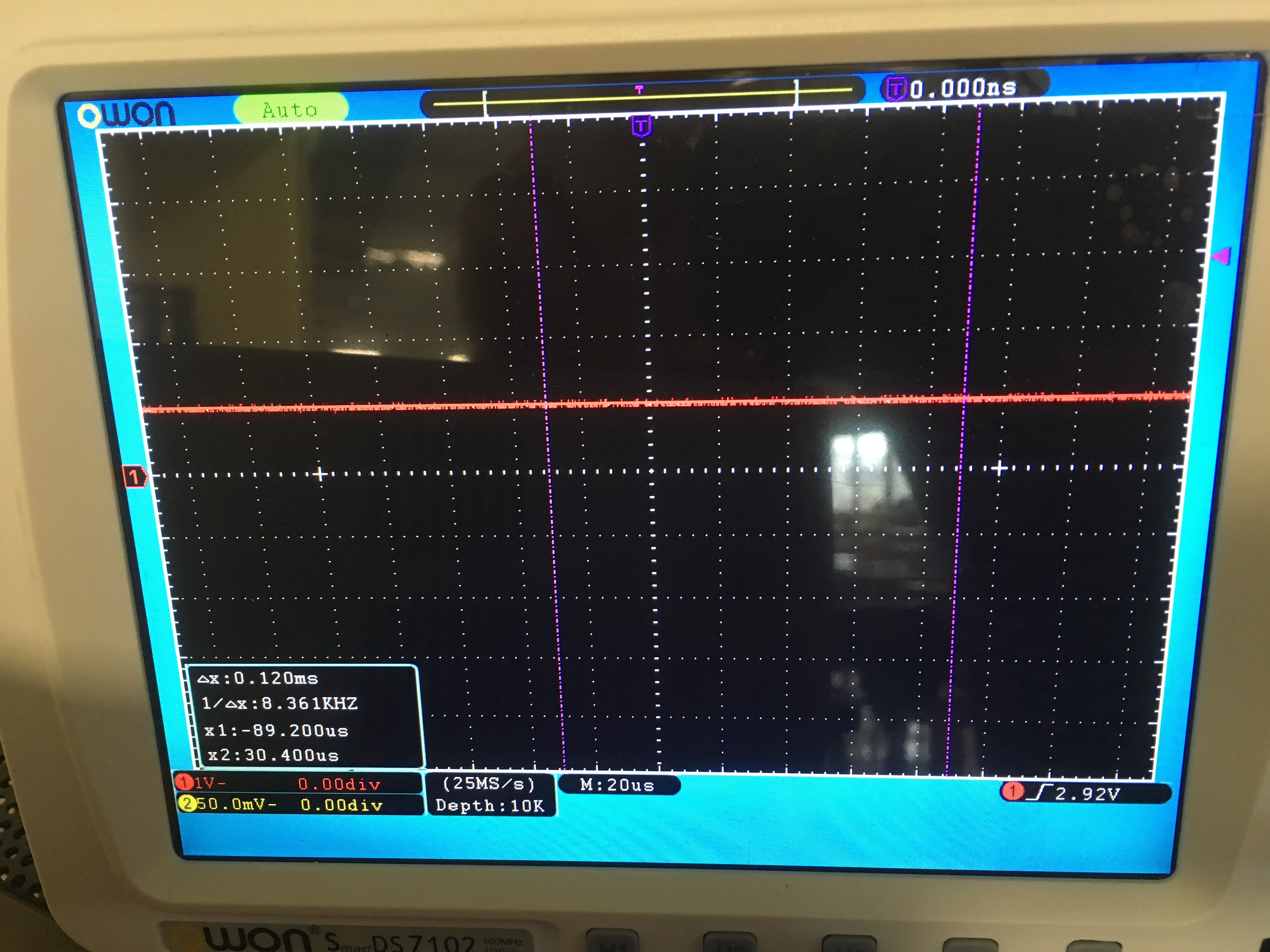
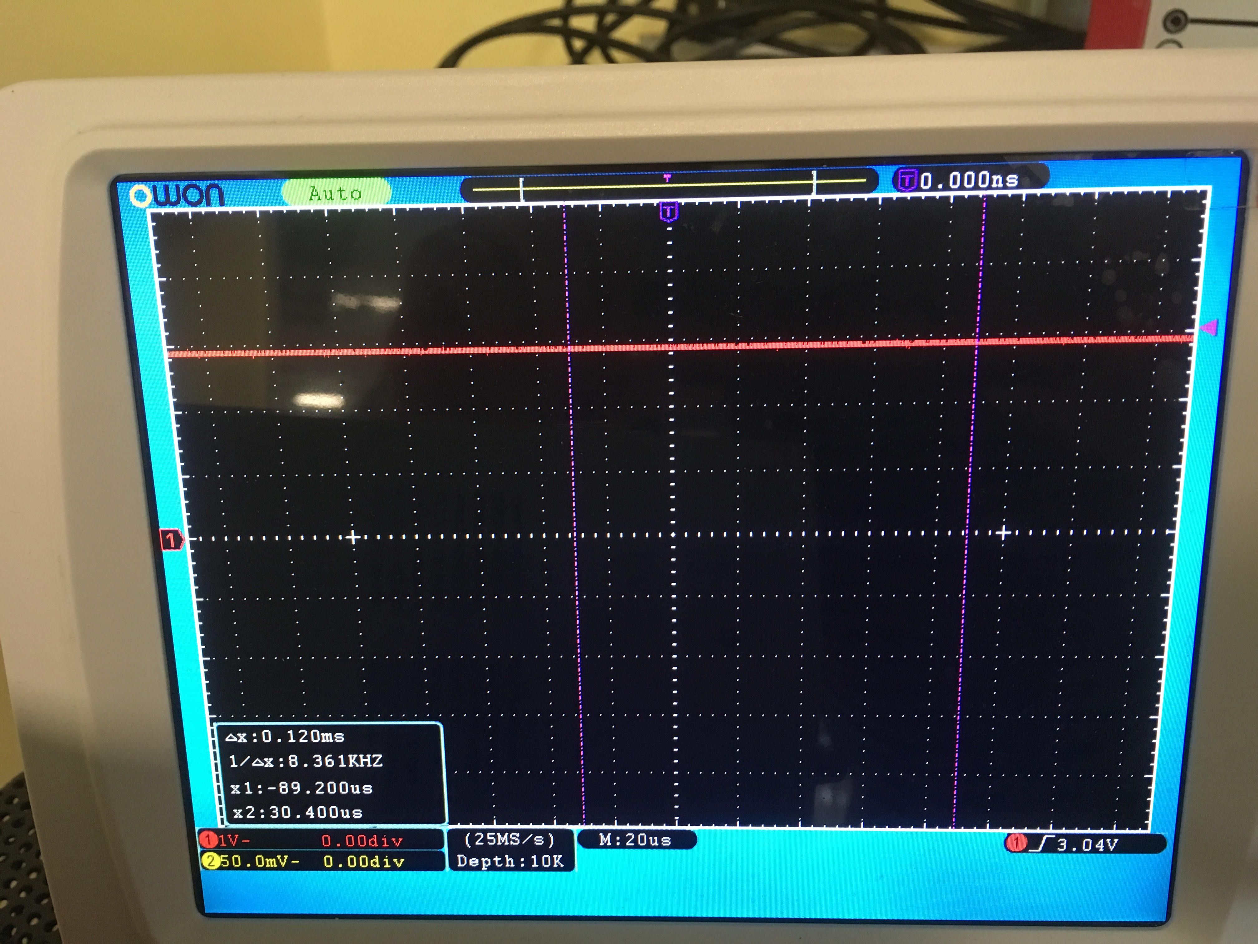
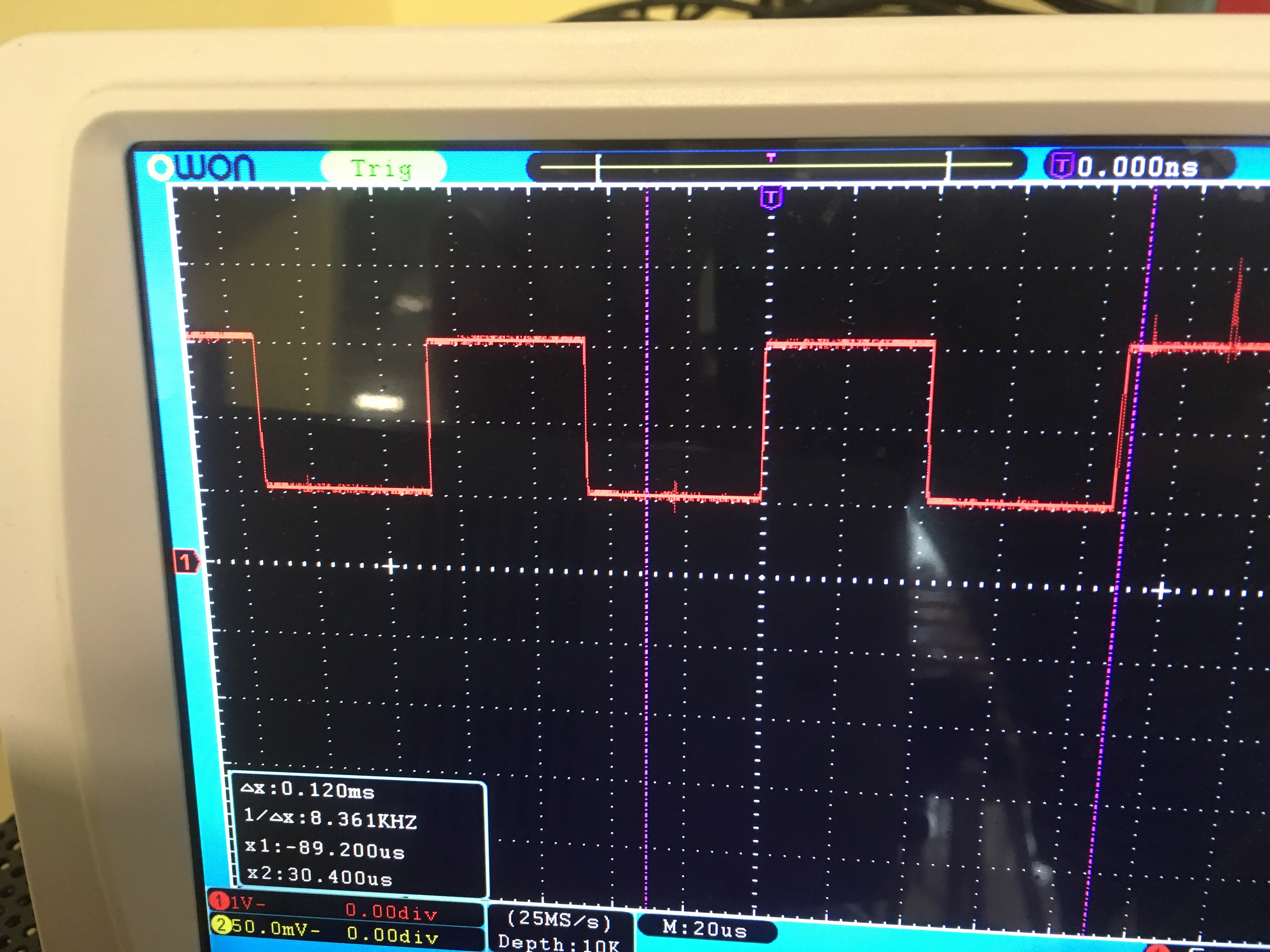
I try to measure the speed of a brushed dc motor using an incremental encoder. I use eCAP module and I have implemented both time difference example and absolute time with Simulink. When I connect the eCAP pin [GPIO5] with GPIOO [PWM1]  then I am able to measure the period of the signal. Unfortunately, when I use the signal from the encoder the system get stuck and Simulink loses control. The signal from the encoder as I capture it with the oscilloscope is the following: 

I am wondering why the signal is starting from 1V and not from zero? Is that a problem? When Simulink loses control the DSP keeps working and I am able to change the motor speed but there are times where the speed it isn' t stable. The higher the frequency the speed gets more stable. 

The pull-up resistor is enabled. 

  • Hi Kostas,


    Did you have any pull up enabled or any other circuitry connected to the pin?
    That might be the reason for non-zero voltage at the beginning.
    Can you make sure that the eCAP counters are not overflowing at lower speeds?
    For your testing, you can input similar frequency (as in case of low speed condition with encoder), from PWM and check that the measurements are as expected.

    -Bharathi.
  • Yes the pull up resistor is enabled [GpioCtrlRegs.GPAPUD.bit.GPIO5 = 0;   /* Enable pull-up on GPIO5 (CAP1)*/].

    I use a voltage divider in order to low the incoming voltage from 5V to 3V [input pulse A from encoder].

    Is this "normal" the pulse to have one voltage offset not only in the beginning but later as well? Maybe this is why Simulink get stuck?

    It is difficult to check the eCAP counters because Simulink get stuck immediately after external mode has enabled. 

    I have used similar frequencies at low and high speeds [PWM 170Hz to 41KHz] and the results were as expected. 

    Thank you for answering. 

  • Could you check the encoder output signal voltage - not connecting to the device pin?
    You can disable the pull up and observe the results.

    Also, observe if there is any noise on the encoder inputs, even that could cause random behavior.
    If you notice any noise, try to enable the GPIO input qualification to filter it out.

    -Bharathi.
  • Thank you Bharathi.

    Do you know how can I change the pull up from Simulink? By default Simulink enable pull up.
  • Kostas,

    I'm not sure about the configuration in Simulink.
    GPAPUD register by default value should be 1 - i.e. pull up disabled.
    So, something in your configuration is causing to set this bit.

    -Bharathi
  • Hi,

    You may use the System Initialize block and in the exit code section write customer code to disable the pull up.

    This code that will be generated from this block will override the default settings.

    Regards,

    Venkatesh C

  •  Thank you Venkatesh C,

    I ll try it and I ll post. So far I run the model from CCS  and there I change the pull up. The PWM is as expected.

    Kind Regards.