


Part Number: F28M35M52C
Tool/software: Code Composer Studio
1.This is the initial value of the structure used below:ID / MASK / FLAG / DLC / buffer array
#define ACUReqMsg1_Default {0x1,0,MSG_OBJ_RX_INT_ENABLE,8,ACUReqID1.Msg_Data_Buffer}
#define ACUReqMsg2_Default {0x2,0,MSG_OBJ_RX_INT_ENABLE,8,ACUReqID2.Msg_Data_Buffer}
#define ACUReqMsg3_Default {0x3,0,MSG_OBJ_RX_INT_ENABLE,8,ACUReqID3.Msg_Data_Buffer}
#define ACUReqMsg4_Default {0x4,0,MSG_OBJ_RX_INT_ENABLE,8,ACUReqID4.Msg_Data_Buffer}
#define ACUReqMsg5_Default {0x5,0,MSG_OBJ_RX_INT_ENABLE,8,ACUReqID5.Msg_Data_Buffer}
#define ACUReqMsg6_Default {0x6,0,MSG_OBJ_RX_INT_ENABLE,8,ACUReqID6.Msg_Data_Buffer}
#define ACUPubMsg1_Default {0x7,0,MSG_OBJ_NO_FLAGS,8,ACUPubID7.Msg_Data_Buffer}
#define ACUPubMsg2_Default {0x8,0,MSG_OBJ_NO_FLAGS,8,ACUPubID8.Msg_Data_Buffer}
#define ACUPubMsg3_Default {0x9,0,MSG_OBJ_NO_FLAGS,8,ACUPubID9.Msg_Data_Buffer}
#define ACUPubMsg4_Default {0xA,0,MSG_OBJ_NO_FLAGS,8,ACUPubIDA.Msg_Data_Buffer}
2.Function Configuration, mailbox 7/8/9/10 set the remote frame automatically reply:
void ConfigureCAN_CR250(void)
{
SysCtlPeripheralEnable(SYSCTL_PERIPH_GPIOE);//CAN0 on GPIOE
GPIOPinConfigure(GPIO_PE6_CAN0RX);//CANRXA
GPIOPinConfigure(GPIO_PE7_CAN0TX);//CANTXA
GPIOPinTypeCAN(GPIO_PORTE_BASE, GPIO_PIN_6 | GPIO_PIN_7);
SysCtlPeripheralEnable(SYSCTL_PERIPH_CAN0);
CANInit(CAN0_BASE);
//Normal Operating Mode ,Initialization, Software Reset, Reset All Message Objects ,Clear Interrupt Pending Bit
CANClkSourceSelect(CAN0_BASE, CAN_CLK_M3);//use M3 system clock
CANBitRateSet(CAN0_BASE, SysCtlClockGet(SYSTEM_CLOCK_SPEED), 500000);
//control message
CANMessageSet(CAN0_BASE, 1, &ACUReqMsg1_CR250, MSG_OBJ_TYPE_RX);
CANMessageSet(CAN0_BASE, 2, &ACUReqMsg2_CR250, MSG_OBJ_TYPE_RX);
CANMessageSet(CAN0_BASE, 3, &ACUReqMsg3_CR250, MSG_OBJ_TYPE_RX);
CANMessageSet(CAN0_BASE, 4, &ACUReqMsg4_CR250, MSG_OBJ_TYPE_RX);
CANMessageSet(CAN0_BASE, 5, &ACUReqMsg5_CR250, MSG_OBJ_TYPE_RX);
CANMessageSet(CAN0_BASE, 6, &ACUReqMsg6_CR250, MSG_OBJ_TYPE_RX);
//status message
CANMessageSet(CAN0_BASE, 7, &ACUPubMsg1_CR250, MSG_OBJ_TYPE_RXTX_REMOTE);
CANMessageSet(CAN0_BASE, 8, &ACUPubMsg2_CR250, MSG_OBJ_TYPE_RXTX_REMOTE);
CANMessageSet(CAN0_BASE, 9, &ACUPubMsg3_CR250, MSG_OBJ_TYPE_RXTX_REMOTE);
CANMessageSet(CAN0_BASE, 10, &ACUPubMsg4_CR250, MSG_OBJ_TYPE_RXTX_REMOTE);
CANIntEnable(CAN0_BASE, CAN_INT_MASTER | CAN_INT_ERROR | CAN_INT_STATUS);
// Enables error and status interrupts and interrupts on interrupt line CANOINT/CAN1INT
IntRegister(INT_CAN0INT0, CANIntHandler0);// Set the interrupt handler on the NVIC
IntEnable(INT_CAN0INT0);// Enable CAN interrupt on NVIC
CANEnable(CAN0_BASE);// un-initialized to enable CAN
}
3、The test data is as follows: After sending 0xA remote frame, the data frame returned is 0x8
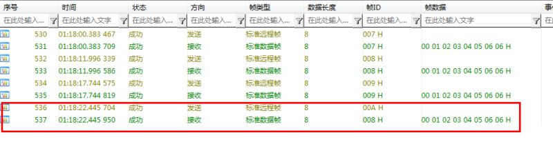
The yellow means send
The green means receive

