- Ask a related questionWhat is a related question?A related question is a question created from another question. When the related question is created, it will be automatically linked to the original question.
Tool/software: Code Composer Studio
Hello All,
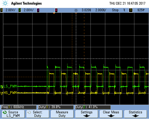
I am configuring a complimentary PWMs (high side adn low side) for a half-bridge converter.
The frequency and dead time are correct until the falling edge of the third EPMW1B(LS). The code for the EPWM is attached below. The complementary EPWM is generated from the dead band module.
I am wondering if the startup behavior of EPWM is controlled and which registers are related to?
(*ePWM[n]).TBCTL.bit.PRDLD = TB_SHADOW; // set load on CTR=0
(*ePWM[n]).TBPRD = period-1; // PWM frequency = 1 / period
(*ePWM[n]).TBPHS.half.TBPHS = 0;
(*ePWM[n]).TBCTR = 0;
(*ePWM[n]).TBCTL.bit.CTRMODE = TB_COUNT_UP;
(*ePWM[n]).TBCTL.bit.HSPCLKDIV = TB_DIV1;
(*ePWM[n]).TBCTL.bit.CLKDIV = TB_DIV1;
(*ePWM[n]).TBCTL.bit.PHSEN = TB_DISABLE;
(*ePWM[n]).TBCTL.bit.SYNCOSEL = TB_CTR_ZERO; // sync "down-stream"
// Counter Compare Submodule Registers
(*ePWM[n]).CMPA.half.CMPA = period/2-1; // set duty 50% initially
(*ePWM[n]).CMPB = 0; // set duty 0% initially
(*ePWM[n]).CMPCTL.bit.SHDWAMODE = CC_SHADOW;
(*ePWM[n]).CMPCTL.bit.LOADAMODE = CC_CTR_PRD;
// Action Qualifier SubModule Registers
(*ePWM[n]).AQCTLA.bit.ZRO = AQ_SET;
(*ePWM[n]).AQCTLA.bit.CAU = AQ_CLEAR;
(*ePWM[n]).AQCTLB.bit.ZRO = AQ_NO_ACTION;
(*ePWM[n]).AQCTLB.bit.CAU = AQ_NO_ACTION;
(*ePWM[n]).AQCTLB.bit.PRD = AQ_NO_ACTION;
// Active high complementary PWMs - Set up the deadband
(*ePWM[n]).DBCTL.bit.IN_MODE = DBA_ALL;
(*ePWM[n]).DBCTL.bit.OUT_MODE = DB_FULL_ENABLE;
(*ePWM[n]).DBCTL.bit.POLSEL = DB_ACTV_HIC;
(*ePWM[n]).DBRED = 10;
(*ePWM[n]).DBFED = 10;
Thank you!
Tian