This thread has been locked.

If you have a related question, please click the "Ask a related question" button in the top right corner. The newly created question will be automatically linked to this question.

CCS/TMS320F28069M: Why at reset vector location braching instructions is not there ?

Part Number: TMS320F28069M
Other Parts Discussed in Thread: CONTROLSUITE, C2000WARE

Tool/software: Code Composer Studio

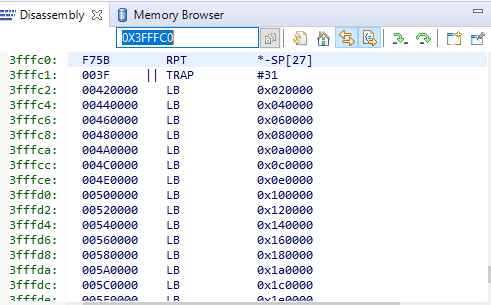
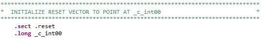
in documents its mention that when device reset the reset vector fetched from the reset vector location , but when I am debugging there is no branching  instruction in reset vector location 0x3fffc0

I am confused how it is working and in the boot28.asm code below line is there , that means it will skip the inbuilt boot rom execution , am I correct ?

can any one explain the these things

  • Hi Veerendra,

    Not very clear on your query. Also the code snapshot is not available in your post. Can you open the disassembly window in CCS and then apply debug reset and check the instruction.

    When connected with debugger and load the code (or restart), CCS forces the PC to entry point and start execution from there. Depending on the setting for the entry point in project, execution of ROM code may be skipped.

    Regards,
    Vivek Singh
  • Verendra,
    The device has the default vector table in ROM populated by factory (TI). On C28, there is NO fetch of instruction from the reset entry location in the vector table, instead the reset entry location of the vector table in ROM contains the address of the boot ROM entry function.

    With debugger connected, when you look at the disassembly window, the address where the PC points to on a reset is the entry point function of the boot ROM SW.

    Now coming to your other question on how it is works - the device boot ROM execution cannot be skipped when device is powered up. By the time the emulator is connected the device boot ROM would have already executed. Also after a reset (external reset, XRSn) the device boot ROM cannot be skipped when running stand-alone.

    With emulator connected when user does a debug reset via CCS, then the device resets and halts at the entry point of the boot ROM SW. Now if user hits run in debugger IDE then device boot ROM is executed but instead if user does a program load (or a restart) then the PC is pointed to the application (user SW) entry point. Defining the application entry point is upto the user and can be done using CCS project properties window. The default TI provided examples use a reset_handler entry point which in turn calls into the _cint00 RTS support library entry point, which in turn calls into the main(). If user doesn't define any entry point to the application then the default _cint00 will be chosen.

    Now how does the boot ROM SW, which is always run after the MCU is reset or powered up, calls into the application entry point? This will be explained in the device TRM boot ROM chapter. In short depending on the boot mode the boot ROM ends up branching in to the entry point for the selected boot mode. User is supposed to have the user application entry point here. Users can refer to TI provided examples in ControlSuite or C2000Ware and put the reset_handler routine in the entry point location.


    Hope this helps.

    Please let us know if you have any further questions.

    Best Regards
    Santosh Athuru.
  •   i am sorry about that , i thought the pictures are attached but not !!!

  • Thank you for answer , but the at reset vector location, ididn't find any branching instruction
    ( i attached the picture below )
  • Veerendra,

    at 0x3FFFC0, you will see the 32-bit address of the boot ROM entry point, not a branch instruction. From the snapshot you put that address is 0x003FF75B.

    Best Regards

    Santosh Athuru

  • I hope this issue is resolved. If not, please let us know further queries else mark this resolved.