This thread has been locked.

If you have a related question, please click the "Ask a related question" button in the top right corner. The newly created question will be automatically linked to this question.

TMS320F28335: ADC to DMA data transfer issue

Part Number: TMS320F28335

hi,

I'm doing a small experiment on DMA and ADC using example code. Example code name is Example_2833xAdcToDMA and this is converting ADC channel 0 to 4 in SEQ1 and transferring it to the DMA. 

now i have changed the code little bit by changing ADC channel select from 8 to 4. Also i have done necessary changes in DMA configuration as follow,

 InitAdc();  // For this example, init the ADC

// Specific ADC setup for this example:
   AdcRegs.ADCTRL1.bit.ACQ_PS = ADC_SHCLK;
   AdcRegs.ADCTRL3.bit.ADCCLKPS = ADC_CKPS;
   AdcRegs.ADCTRL1.bit.SEQ_CASC = 0;        // 0 Non-Cascaded Mode
   AdcRegs.ADCTRL2.bit.INT_ENA_SEQ1 = 0x1;
   AdcRegs.ADCTRL2.bit.RST_SEQ1 = 0x1;
   AdcRegs.ADCCHSELSEQ1.bit.CONV00 = 0x0;
   AdcRegs.ADCCHSELSEQ1.bit.CONV01 = 0x1;
   AdcRegs.ADCCHSELSEQ1.bit.CONV02 = 0x2;
   AdcRegs.ADCCHSELSEQ1.bit.CONV03 = 0x3;
   AdcRegs.ADCMAXCONV.bit.MAX_CONV1 = 3;   // Set up ADC to perform 4 conversions for every SOC

//Step 5. User specific code, enable interrupts:
  // Initialize DMA
	DMAInitialize();

	// Clear Table
   for (i=0; i<BUF_SIZE; i++)
   {
     DMABuf1[i] = 0;
   }

// Configure DMA Channel
    DMADest   = &DMABuf1[0];              //Point DMA destination to the beginning of the array
	DMASource = &AdcMirror.ADCRESULT0;    //Point DMA source to ADC result register base
	DMACH1AddrConfig(DMADest,DMASource);
	DMACH1BurstConfig(3,1,10);
	DMACH1TransferConfig(9,0,0);
	DMACH1WrapConfig(0,0,0,1);			
	DMACH1ModeConfig(DMA_SEQ1INT,PERINT_ENABLE,ONESHOT_DISABLE,CONT_DISABLE,SYNC_DISABLE,SYNC_SRC,
	                 OVRFLOW_DISABLE,SIXTEEN_BIT,CHINT_END,CHINT_ENABLE);

	StartDMACH1();

Remaining code and settings are same. the problem i'm facing here is ADC conversion placed properly at RAM on 1st trigger and on 2nd trigger its places previous ADC data. so ADC result placed at DMA RAM every alternate trigger . What could be the possible causes? is that possible to use ADC only for the first 4 conversion and on next trigger, conversion will start from the CH0?

  • Hi Pritesh,

    A TI engineer has been assigned to help with your issue. The response may be delayed due to the holiday. Thanks for your patience.

    Best regards,
    Chen
  • Pritesh,

    It looks to me like SOC_SEQ2 is never triggered in the example so the DMA is likely already configured to handle just the 4 conversions on SOC_SEQ1.

    -Tommy

  • Hi Tommy,

    Thanks for your response.

    I'm not triggering SEQ2 anyway. i'm talking in reference to the default example of ADC to DMA and my code(i.e. small change in example code).

    1st trigger to ADC means software trigger to SEQ1, and similarly 2nd trigger to ADC means software trigger to SEQ1. As we can see in the example code all triggers run by small delay using for loop.

    Thank You,

    Pritesh

  • Pritesh,

    I believe that the example is already configured to process 4 conversions on SEQ1 as you wish to do. If true, you should not need to modify any of the DMA settings.

    -Tommy
  • Hi Tommy,

    You are right! example code is already configured for the 4 channel. But what my query is, is that possible to assign only 4 channel to SEQ1 instead of all 8 channel? This is for the core level understanding of DMA and ADC both.

    with my understanding example code has assigned all the ADCCHSEQ as follows,

       AdcRegs.ADCCHSELSEQ1.bit.CONV00 = 0x0;
       AdcRegs.ADCCHSELSEQ1.bit.CONV01 = 0x1;
       AdcRegs.ADCCHSELSEQ1.bit.CONV02 = 0x2;
       AdcRegs.ADCCHSELSEQ1.bit.CONV03 = 0x3;
       AdcRegs.ADCCHSELSEQ2.bit.CONV04 = 0x0;
       AdcRegs.ADCCHSELSEQ2.bit.CONV05 = 0x1;
       AdcRegs.ADCCHSELSEQ2.bit.CONV06 = 0x2;
       AdcRegs.ADCCHSELSEQ2.bit.CONV07 = 0x3;

    where on first trigger to ADC will perform conversion 0-3 and one second trigger it performs the conversion 4-7 and then source address in DMA wrapping to ADCRESULT0.

    where as for the core understanding of DMA and ADC, i would like to assign only 4 channel to ADCCHSELSEQ as follows,

       AdcRegs.ADCCHSELSEQ1.bit.CONV00 = 0x0;
       AdcRegs.ADCCHSELSEQ1.bit.CONV01 = 0x1;
       AdcRegs.ADCCHSELSEQ1.bit.CONV02 = 0x2;
       AdcRegs.ADCCHSELSEQ1.bit.CONV03 = 0x3;

    where on first trigger to ADC will perform conversion 0-3 and then source address in DMA wrapping to ADCRESULT0. so i want wrapping of DMA source address at every ADC trigger as per my setting if it is possible not unlike above case.

    Thank you,

    Pritesh

  • Pritesh,

    For the ADC you would just need to enable continuous run using CONT_RUN so that each SOC will start from CONV00.

    -Tommy 

  • Dear Tommy,

    I have tried the CONT_RUN and its not solving my problem. Also the given solution focuses only on ADC configuration not an overall aspect i.e, along with the example. I wish your team take a look at the problem mentioned and come back with sufficient time.

    Thank you,

    Pritesh

  • Hi Pritesh,

    It's not clear to me what you're saying the issue is. Is it the source address that does not appear to be wrapping properly? If so, perhaps you could disable wrapping (set the source wrap size to all 1s) and use a negative source transfer step (-3?) to get you back to ADCRESULT0? Since you want it to happen every burst, and you're always going back to the same address, using wrap shouldn't be necessary.

    Or am I misunderstanding the issue? Does it appear to be an issue with the trigger itself and not the way the DMA is incrementing/wrapping addresses?

    Whitney
  • I should mention that I don't actually see anything wrong with the way you've configured the DMA currently, but I thought it might be a good experiment to try it without the wrap as I described above.

    Whitney
  • 
    

    Dear Whitney,
    Thanking you for your response and suggested solution.
    "Is it the source address that does not appear to be wrapping properly?"

    Yes sort of i can say that Source address is not wrapping to the ADCRESULT0. Now i can't identify weather its because of ADC or because of DMA? the configuration of both ADC and DMA shown at the top in question. 

    "perhaps you could disable wrapping (set the source wrap size to all 1s) and use a negative source transfer step (-3?) "
    i have done so by configuring the DMA as follow

    DMACH1TransferConfig(9,-3,0);
    DMACH1WrapConfig(65535,0,0,1);

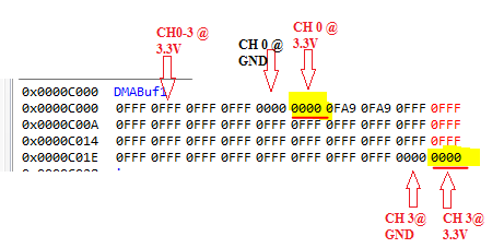
    after suggested solution of disabling source wrap and source transfer step to -3, it behaves the same as earlier. for more understanding i have attached the DMA buffer result and we can see below that the Data of ADC updated at DMA memory every alternate trigger of ADC and not every time.

    I'am really not sure that it is because of the ADC architecture in TMS320f28335 or still we can achieve the result by configuring DMA. is i misunderstood anything? i hope you understand the problem in this case clearly? Is it possible from your side to just run the example code and my updated code? it may give clear understanding if i could not be able to explain.

    Thanks 

    Pritesh

     Is it the source address that does not appear to be wrapping properly? 

  • Thanks for the memory snapshot. That helps. It almost looks like you're getting two DMA triggers for every sequence. Would you agree?

    I'll need to track down an F28335 board to try out your ADC code, but I did run your DMA code on another board (the DMA is pretty much the same on all C2000 devices) and it worked as expected for me.

    Whitney

  • Hi Pritesh,

    Were you able to find a solution to this issue?

    Edit: I'm going to close the thread since we haven't heard back from you, but please feel free to comment to reopen it if you still need assistance.

    Whitney