This thread has been locked.

If you have a related question, please click the "Ask a related question" button in the top right corner. The newly created question will be automatically linked to this question.

TMS320F28335: F28335 does not generate Clock Signal on SCL line of I2C bus

Part Number: TMS320F28335
Other Parts Discussed in Thread: LM75B, CONTROLSUITE

Hi, 

I try to communicate with 6 slave LM75B by using I2C peripheral of F28335. f28335 is master and LM75B's are slave. However, F28335 can not genarate clock signal on SCL pin  despite I put the data I2CDXR register. So, Interrupt is not generated.

I tried with different pull-up resistors but i could not solve the problem. What can be the reason of this problem?

Any help will be appreciated.

Thanks.

Sertac

  • Sertac,

    Have you verified that you have configured the GPIO mux options for the F28335? By default, all GPIOs are configured as digital inputs. You need to adjust the GPxMUX register to the appropriate value.

    Thanks,
    Mark
  • Mark,

    I configure the GPIO registers as shown below. Is there any problem  ?

    GpioCtrlRegs.GPBPUD.bit.GPIO32 = 1; // Disable pull-up for GPIO32 (SDAA)
    GpioCtrlRegs.GPBPUD.bit.GPIO33 = 1; // Disable pull-up for GPIO33 (SCLA)
    /* Set qualification for selected pins to asynch only */
    // This will select asynch (no qualification) for the selected pins.
    GpioCtrlRegs.GPBQSEL1.bit.GPIO32 = 3; // Asynch input GPIO32 (SDAA)
    GpioCtrlRegs.GPBQSEL1.bit.GPIO33 = 3; // Asynch input GPIO33 (SCLA)
    /* Configure SCI pins using GPIO regs */
    // This specifies which of the possible GPIO pins will be I2C functional pins.
    GpioCtrlRegs.GPBMUX1.bit.GPIO32 = 1; // Configure GPIO32 for SDAA operation
    GpioCtrlRegs.GPBMUX1.bit.GPIO33 = 1; // Configure GPIO33 for SCLA operation

    Thnaks

    Sertac

  • Sertac,

    Have you placed and EALLOW instruction before configuring the GPIOs?
    What is the value of the external pullups that you have used on the signal lines?

    Have you used this module before with success? If you run the example in controlsuite you can verify and compare that your configurations are similar.

    Thanks,
    Mark
  • Mark,

    I use EDIS and EALLOW for GPIO register configs. I have 10 k pull up resistor. 

    I used this module before with success but the I2C IC was different. I load that code but unfortunately it does not work on new hardware too. 

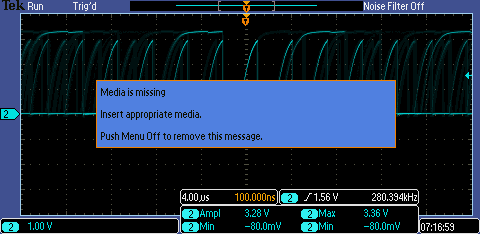
    I run the example in constrol suite but I see clock signal attached in the figure. 

    Thanks

    Sertac

  • Sertac,
    To be clear, when you run the example, you see the clock toggle? If you run your code standalone (no slaves connected) are you able to see the clocks being driven?

    It is hard to say what the issue is here, but I would look at your slave network. If you can run example code with the C2000 I2C and see the data and clock transition as you expect then connect the slaves and it no longer works, there might be something preventing the line from being pulled low.

    Is this completely custom hardware or is it a few evaluation boards wired together?


    Thanks,
    Mark
  • Sertac,

    It has been over a week since your last reply, so I am assuming that you were able to resolve your issue. If this isn't the case, please reject this resolution or reply to this thread. If this thread locks, please make a new thread describing the current status of your issue.

    Thanks,
    Mark
  • Mark,

    Sorry for late reply.

    I resolved the problem. But, it is very interesting that despite the clock signal attached in my previous post , F28335 generated interrupt and receive data from slave. SDA and SCL lines signals are overlapping in the figure I send with previous post.

    I think the probe of oscilloscope causes this. It monitors both SDA and SCL line despite I only connect one of them.

    Thanks

    Sertac
  • Sertac,

    I am glad that you were able to resolve this. Can you share what the issue was in the end?

    Thanks,
    Mark