This thread has been locked.

If you have a related question, please click the "Ask a related question" button in the top right corner. The newly created question will be automatically linked to this question.

TMS320F28031: ADC abnormal behavior when connecting AIO to ground.

Part Number: TMS320F28031
Other Parts Discussed in Thread: TEST2

Hi Champs,

My customer wants to use AIO as GPIO to detect the digital inputs. There are 8 switches on DIP switch, and 6 AIOs are connected to DIP switch as follows. And 1 switch is connected to GPIO, and DIP8 is connect to ADCINB0, which use ADC sampling to detect the switch on or off.

DIP1 AIO6
DIP2 AIO4
DIP3 AIO2
DIP4 AIO10
DIP5 AIO12
DIP6 AIO14
DIP7 GPIO29
DIP8 ADCINB0

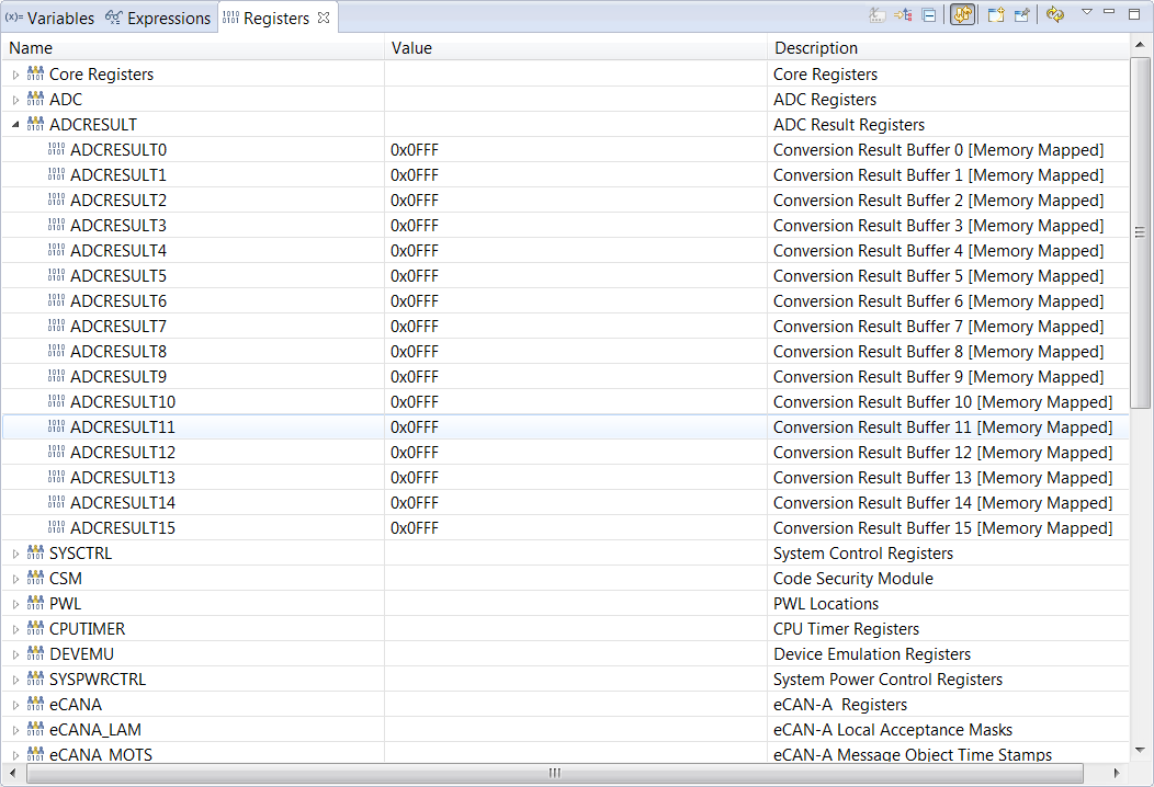
In their design, if switch is turned to ON, AIO will be connected to ground directly. And if switch is turned off, AIO will be pulled to Vcc using 3.3K resistor. If more than 3 AIO are connected to ground, ADC will hang and the content of ADC result registers are 0x0FFF. If turning 1 AIO to ground, ADC will be recovered, but ADC result were abnormal. 

Would you kindly help to explain the root cause of ADC hanging, and also would you suggest how to revise this circuit from silicon aspect?

Thanks a lot.

BR,

Young

  • Young,
    This does sound strange, since these pins are shared with both ADC, Comparator, and AIO; I'd like to eliminate some variables, can customer try/confirm the same behavior happens when the AIO functions are disabled, as well as make sure comparators are off?

    i.e. the only time the ADC is used is to sample B1; but still flip the switches to see if the problem happens again.

    I'm wondering if somehow the customer has enabled the output of the AIO and is driving against ground and we get too much current sink at 3 IOs to ground. I think the easiest way though is to eliminate some variables first.

    Will see what customer finds.

    Best,
    Matthew
  • Hi Matt,

    Thanks for your reply. I have done more testing as follows.

    1. turn off DIP1~DIP8, which means all the ADC pins are pulled high with 3.3K resistors.  A voltage probe is used to monitor the voltage of ADCINB0. ADC_SOC example code is used to test customer's board. Comparator's CLK is disabled.

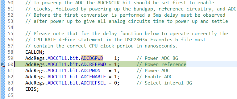
    2 After powering on, ADCINB0's voltage is 3.3V. When PC run to the following code(Band Gap enabled), ADCINB0's voltage is 3.08V.

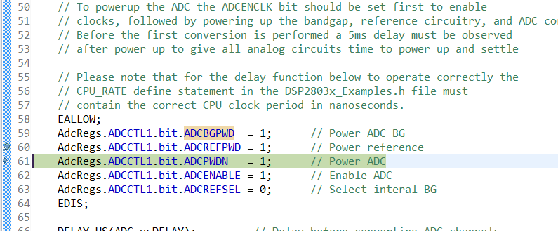
    3. After powering on ADC reference, ADCINB0's voltage is 2.46V.

    4. After powering ADC module, ADCINB0's voltage is 2.23V.

    5. Whether enabling or disabling AIO, the testing results are same.

    6. If removing all the pull-up resisitors except DIP8's and AIO pins are floating, ADCINB0's voltage changes to 1.83V. And ADC sampling result is fixed to 4095.

    7. Other doubtful points: TEST2 pin is connected ground directly, VREFHI is connected to ground directly.

    Thanks.

    BR,

    Young

  • Young,
    I'm checking on TEST2, as you said datasheet requires this pin be left unconnected at all times. I believe from above customer is using the 64 pin package where VREFHI is a shared pin with ADCINA0 so if this is tied to VSSA it is OK as long as external reference is not used.

    Does this happen on multiple devices, or just verified on one device, from the above I'm considering that the device may have been damaged.

    Best,
    Matthew
  • Hi Matt,
    Yesterday customer tested 50 pcs PCBA, and all the boards had the same issue. And issue is "If more than 3 AIO are connected to ground, ADC result registers are 0x0FFF, and can trigger ADC interrupt normally. "
    I have gotten one board, and will start to test in TI lab.
    Thanks.
    Young
  • Young,

    Is there a single ground on the board or is it split between analog and digital ground?

    -Tommy
  • Hi Tommy,

    There is a single ground on the board.

    Thanks.

    BR,

    Young

  • Hi Tommy/Matt,

    Today I tested the code using TI F28035 ControlCard, and all the ADC pins were connected to the ground directly except ADCINB0. And ADCINB0 was pulled high with a 2K Ohm resistor. The example code can work well on ControlCard. 

    Then I removed all the DIP switches of customer's board. After that all the ADC pins would be floating. And all the ADC sampling results are 0x0FFF, even if some of ADC pins were connected to GND.

    At last, I checked the Boot ROM, and found both of customer's F28031 and Controlcard's F28035's OTP checksum were 0xFC00

    Would you kindly help to check the root cause?

    Thanks.

    BR,

    Young

  • Tommy,

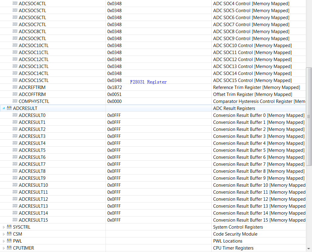
    Please find the customer's F28031's register contents as follows

    Regards,

    Young

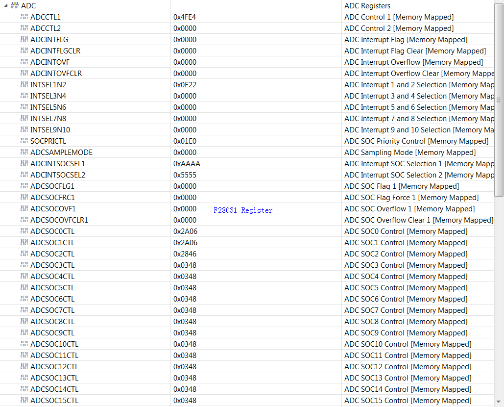
  • Tommy,

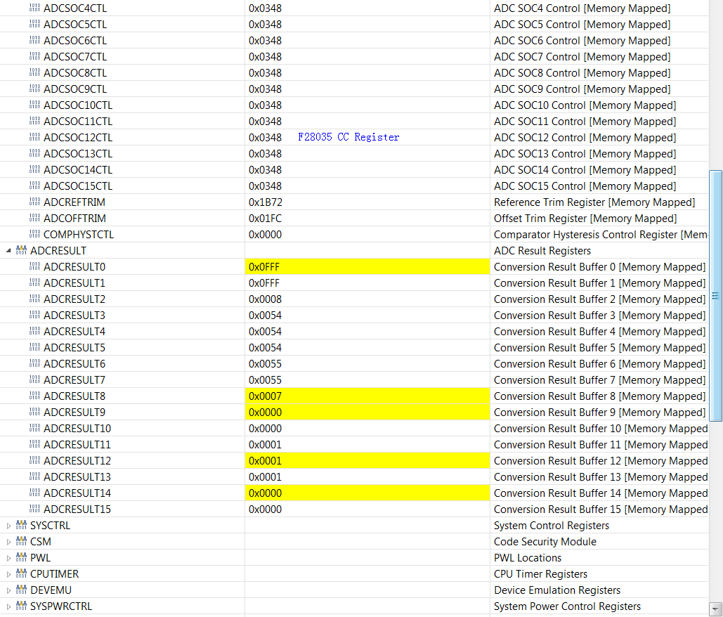
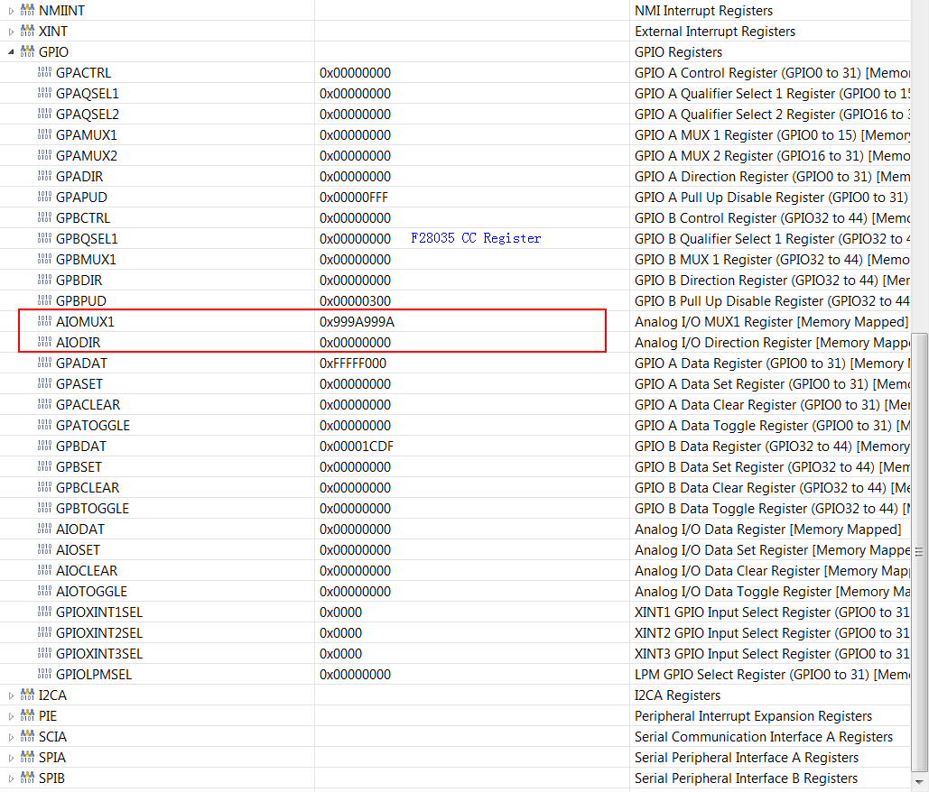
    Please find the TI's F28035 controlcard's register contents as follows

    Regards,

    Young

  • Hi Champs,
    The root cause is customer forgot to connect VDDA with VDD. And this post can be closed.
    Thanks.
    Young