Part Number: TMS320F28069F
Hi there,
I'm designing a dual inverter that has two TMS320F28069F processors on it. I wanted to have a "Global Reset" pushbutton that would reset both MCUs if pressed. Thus both XRS lines are connected together and if the pushbutton is pressed, it will pull the two XRS pins low and reset the MCU.
I thought this would be fine since the pins are open drain, but I'm getting some very strange behavior that I believe is caused by the common XRS line. Right now, I have a simple program on each processor that flashes a orange debug LED. When the board reset lines aren't connected, the programs functions correctly and the debug LED flashes continuously. When the boards reset lines are connected, board 1 flashes its LEDs while board 2 LED is off. Then board 2 LED flashes while board 1 is off. And this alternating pattern continues.
If I take one board off, turn power on, and then plug the other board back in, everything seems to work fine. The problem is when both boards are connected and power is applied. Is this a POR or BOR problem?
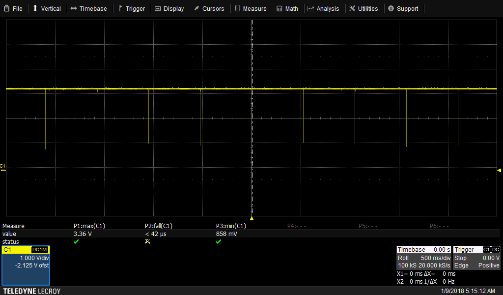
Shown below are the relevant parts of my schematic and then I attached a scope shot of the XRS node. Here is a hyperlink to a video showing the LED behavior. Any advice is greatly appreciated. Thanks!